ABB ACS880 Drive Wiring

Master the installation of your ABB ACS880 VFD. This comprehensive guide covers power wiring, control I/O, Safe Torque Off (STO) connections, and EMC best practices.

ABB ACS880 Drive Wiring

Wiring an ABB ACS880 variable frequency drive (VFD) correctly is the foundation of a reliable, noise-free motor control system. While it might seem as simple as connecting a few power cables and a start switch, modern industrial drives require strict adherence to grounding, shielding, and safety protocols to function flawlessly.

Whether you are replacing an old drive or installing a brand-new panel, this guide will walk you step-by-step through the physical installation of the ACS880—covering power connections, control I/O, the crucial Safe Torque Off (STO) circuit, and best practices for EMC (Electromagnetic Compatibility).

Power Wiring (The Heavy Muscle)

The power wiring section handles the high-voltage grid input and the variable-frequency output to the motor. Proper cable selection and routing here are critical to prevent electrical noise from disrupting your plant.

1. Input Mains Wiring (From the Grid)

  • Route your 3-phase incoming supply through the bottom or top cable entry (depending on your frame size).
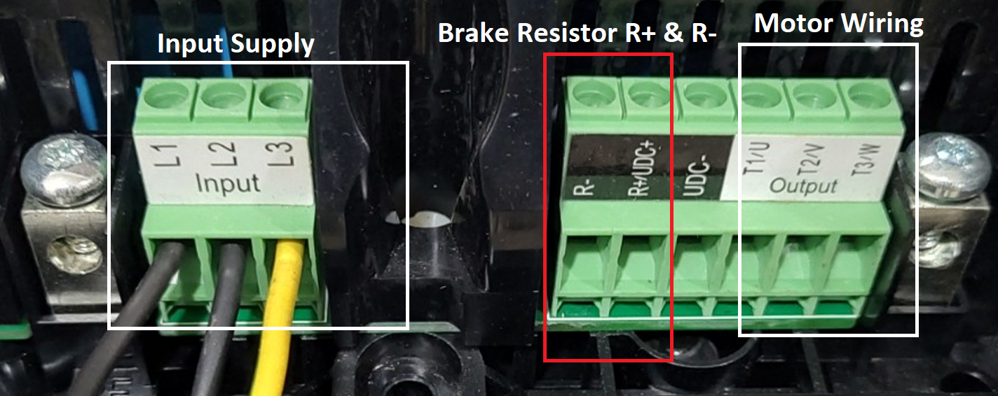
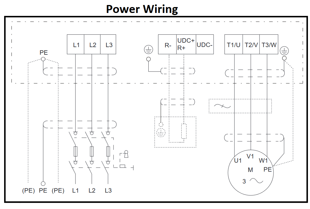
  • Connect the phases to the input terminals marked L1, L2, and L3 (sometimes labeled U1, V1, W1).
  • Connect the supply protective earth (PE) ground wire to the drive’s PE terminal.
abb acs880 control wiring 1 image 12

Power Wiring

abb acs880 drive power wiring image 3
abb acs880 power wiring image 1

2. Motor Output Wiring (To the Motor)

Pro-Tip: You must use symmetrical shielded motor cables (VFD-rated cables) for the ACS880 to meet EMC guidelines and protect motor bearings.

  • Connect the three motor phases to the output terminals marked T1/U2, T2/V2, and T3/W3.
  • 360-Degree Grounding: Strip the outer jacket of the motor cable to expose the braided shield. Clamp this exposed shield directly to the drive’s grounding shelf using the 360-degree grounding clamps provided. This directs high-frequency noise straight to ground.
  • Twist the shield’s copper wires into a “pigtail” and connect it to the PE terminal. Connect the other end of the PE shield to the motor frame.

3. Brake Resistor Wiring (Optional)

If your application involves heavy deceleration (like a crane or centrifuge), you may be using a dynamic brake resistor. Connect the resistor cables to the terminals marked R+ and R-. Ensure these cables are also shielded!

Control Wiring (The Brains)

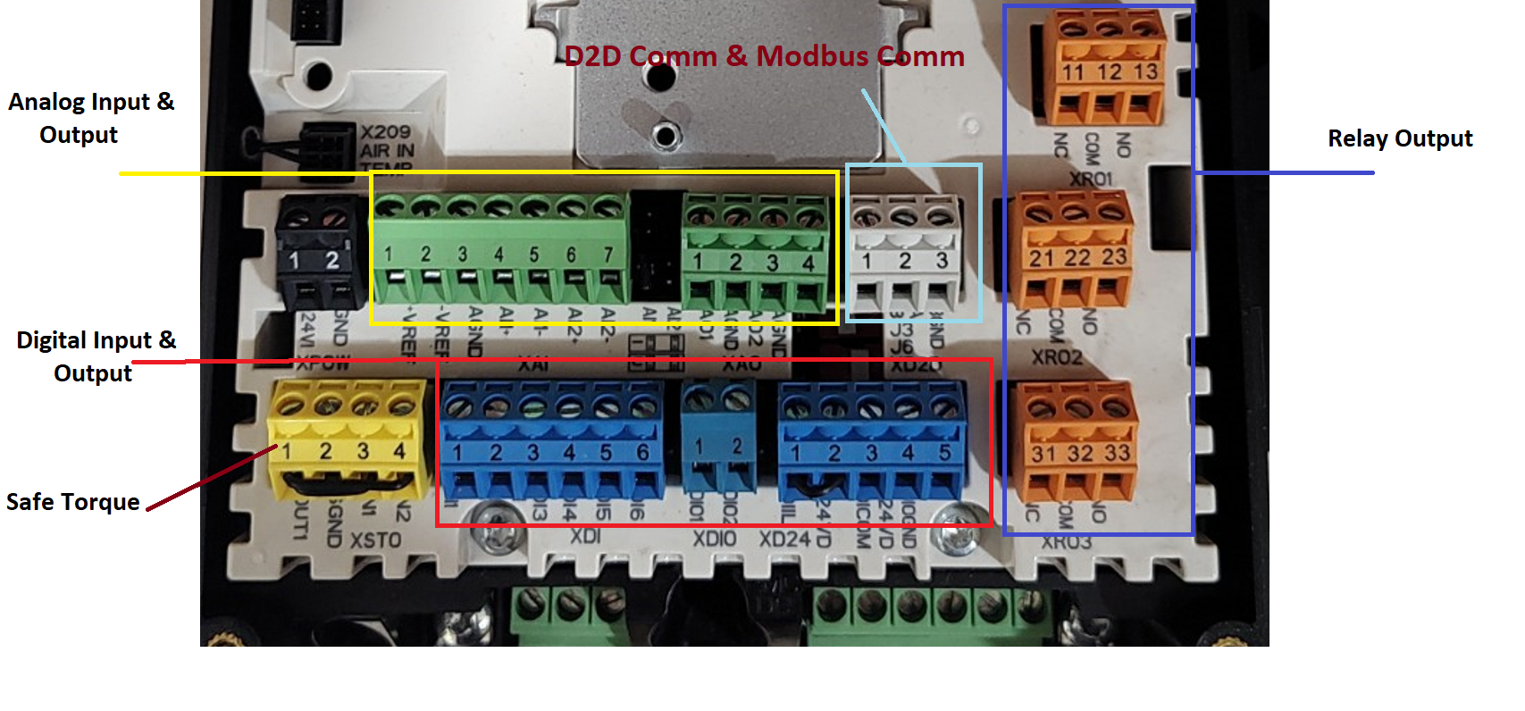
The control board (ZCU or BCU depending on the model) is where you connect your PLCs, switches, sensors, and safety relays. Use twisted-pair shielded cables for all control wiring.

abb acs880 drive 2 wire new
abb acs880 drive factory macro image

1. Safe Torque Off (STO) – Do Not Skip This!

The ACS880 features an integrated Safe Torque Off (STO) function. If the STO circuit is open, the drive will not run and will display an STO fault.

  • If using an external safety relay: Wire your dual-channel safety relay to the STO terminals (usually OUT, SGND, IN1, and IN2). When the safety gate opens, the relay cuts power to IN1 and IN2, safely disabling the drive’s power semiconductors.
  • If NOT using external STO: You must install factory jumpers across the STO terminal block. Jumper OUT to IN1, and OUT to IN2. (Check your specific hardware manual, as terminal block layouts vary slightly by board revision).

2. Digital Inputs (Start/Stop/Direction)

Using the ABB Factory Default Macro, wiring a simple 2-wire start/stop is very easy.

  • 24V Auxiliary Power: The drive provides +24V DC at terminal 10 (XD24 block).
  • Start/Stop (DI1): Run a wire from terminal 10 through your Start/Stop selector switch, and back to DI1 (Terminal 13).
  • Forward/Reverse (DI2): If you need a directional switch, wire from terminal 10 through a switch to DI2 (Terminal 14).

3. Analog Inputs (Speed Reference)

To control the motor’s speed, you’ll wire a 0-10V or 4-20mA signal to Analog Input 1 (AI1).

  • Voltage/Current Switch: On the control board, locate the dip switch or jumper for AI1. Set it to ‘U’ for Voltage (0-10V) or ‘I’ for Current (4-20mA).
  • Wiring a Potentiometer (0-10V):
    • +10V Reference -> Terminal 2
    • Wiper (Signal) -> Terminal 4 (AI1+)
    • Ground -> Terminal 3 (AGND)
  • Wiring a PLC (4-20mA): Connect the positive signal wire to AI1+ (Terminal 4) and the negative return to AI1- (Terminal 5).

4. Relay Outputs (Status Signals)

The ACS880 has programmable relay outputs to send status signals back to your PLC or indicator lights. By default:

  • RO1 (Terminals 21, 22, 23): Indicates “Drive Ready.”
  • RO2 (Terminals 24, 25, 26): Indicates “Drive Running.”
  • RO3 (Terminals 27, 28, 29): Indicates “Drive Faulted.” Wire a panel alarm light to the Normally Open (NO) side of RO3.

Cable Routing & EMC Best Practices

Even with perfect connections, poor cable routing can cause erratic VFD behavior and sensor failures.

  1. Separation of Powers: Never run 24V control cables in the same tray or conduit as 480V motor or power cables. Keep them at least 8 to 12 inches apart.
  2. Cross at 90 Degrees: If a control cable must cross a power cable, make sure they cross at a perpendicular (90-degree) angle to minimize electromagnetic interference.
  3. Ground Control Shields at One End: To prevent ground loops, ground the shield of your control cables at the drive end only. Cut and tape the shield at the sensor/switch end.

Ready to Power Up

Double-check all terminal tightness (loose connections cause arcing and heat!), ensure no stray copper strands are touching adjacent terminals, and verify your STO jumpers or safety relay wiring is secure.