Hitachi SJ-P1 Drive – Find comprehensive resources for Hitachi SJ-P1 AC drives, including product catalogs, manuals, price list, programming guides, fault, alarm, warnings & software support. Get expert assistance for troubleshooting and optimization.
Hitachi SJ-P1 drive is a high-performance variable frequency drive (VFD) designed for demanding industrial applications. It’s designed for applications requiring precise control and high performance.
Power rating:
- 0.7 ~ 160 kW (3-phase 400V)
- 0.4 ~ 75 kW (3-phase 200V)
Features
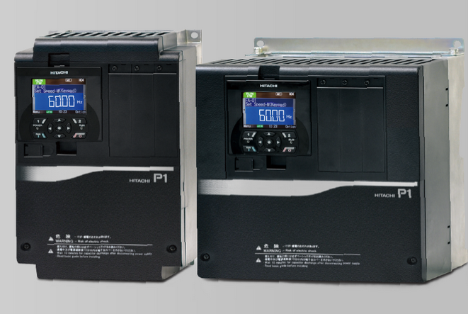
Hitachi SJ-P1 Drive comes with its intuitively designed LCD color removable operator panel, this drive will serve your most demanding applications. The SJ-P1 multi-mode operation can be used with many optional cassettes to configure the drive to your specific needs.
- Heat sink designed for external mounting if required
- RS-485 Modbus RTU standard
- Energy saving function standard
- Keypad /Terminal switching
- Three-wire operation function
- Standard LCD color operator
- PID, Logic and time delay functions built in
- Arithmetic operation and delay functions
- Error codes in text
- Analog input disconnection detect function
- CE/UL/cUL/c-Tick approvals
- 10 year MTBF life design
- Loss of signal protection
- Sink or Source input compatible
- EzCOM for drive to drive master-less communications
- PID Sleep mode function and loss of pressure function
- PMAC motor compatible
Applications
- Conveyors and Conveying Equipment
- Extrusion Equipment
- Irrigation Applications
- Laundry and Dry Cleaning
- Overhead Traveling Hoist Systems
Specifications
| Items | General Specifications | |||||
| PWM system | Sine-wave PWM system | |||||
| Output frequency range | 0.00 to 590.00Hz | |||||
| Frequency accuracy | For the highest frequency, digital ±0.01%, analogue ±0.2% (25±10℃) | |||||
| Frequency resolution | Digital: 0.01Hz, Analogue: Max. frequency / 4000 (Ai1 terminal / Ai2 terminal: 12 bit / 0 to +10V or 0 to +20 mA, Ai3 terminal: 12 bit / -10 to +10V) | |||||
| Control system | IM | V/f control (constant torque/reduced torque/ free / automatic boost control ) V/f with encoder( constant torque/reduced torque/ free / automatic boost control ) Cascade type sensorless vector control, 0Hz sensorless vector control, Vector control with encoder | ||||
| SM/PMM | Synchronous startup for smart sensorless vector control , IVMS start type sensorless vector control | |||||
| Speed fluctuation | ±0.5% (sensorless vector control) | |||||
| Acceleration/deceleration time | 0.00 to 3600.00s (Linear, S-curve, U-curve, Inverted-U-curve, EL-S-curve) | |||||
| Display | Output frequency, Output current, output torque, trip history, input/output terminal function, input/output power, PN voltage, etc. | |||||
| Start functions | DC braking after the start, matching frequency after the start, active frequency matching start, Low-voltage start, retry restart. | |||||
| Stop functions | After free run stop, deceleration stop; DC braking or external DC braking operation (Braking force, time, adjustment of operation speed) | |||||
| Stall prevention function | Overload limit function, overcurrent supression, overvoltage suppresion function | |||||
| Protection functions | Overcurrent error, Overload error, Brake resistor overload,Overvoltage error, Memory error, Undervoltage error, Current detector error, CPU error, External trip error, USP error, Ground error, Supply overvoltage error, Power loss error, Temperature detectorerror, Cooling-fan rotation speed decrease temperature error, Temperature error, Input open-phase error, IGBT error, Output open-phase error, Thermistor error, brake error, low-speed range overload error, Controller overload error, RS485communication error, RTC error, EzSQ related error, option related error, functional safety related error, position control range error, speed deviation error, position deviation error, overspeed error, contactor error, PID start error. | |||||
| Other functions | V/f free setting (7 points), upper and lower frequency limit, frequency jump, curve acceleration and deceleration, manual torque boost, energy- saving operation, analogue output adjustment, minimum speed, carrier frequency adjustment, motor electronic thermal function(free is possible), inverter thermal function, external start-end(speed and rate), frequency input selection, trip retry, restart stop, various signal output, initialization setting, PID control, auto-decel at shut-off, brake control function, commercial switching function, auto-tuning (on/offline) etc. | |||||
| Input | Frequency setting | Panel | Up, down left and right keys to the set parameter. | |||
| External signal | Ai1 / Ai2 terminal (Current and Voltage is able to switched.) | 0 to 10Vdc (input impedance: 10kΩ) / 0 to 20mA (input impedance: 100Ω) | ||||
| Ai3 terminal | -10 to +10Vdc (Input impedance: 10kΩ) | |||||
| Multi-speed terminal | 16multi-speed (With the use of the intelligent input terminal) | |||||
| Pulse train-input | Maximum 32 kHz ×2 | |||||
| External port | RS485serial communication (Protocol: Modbus-RTU, Maximum: 115.2kbps) | |||||
| Forward / reverse Start / stop | Panel | By RUN / Stop key (With the set parameter, forward / reverse can be switched) | ||||
| External signal | Forward (FW) / Reverse (RV) / 3-wire input allowed (STA,STP,FR) (When input terminal functions are assigned) | |||||
| External port | RS485serial communication (Protocol: Modbus-RTU, Maximum: 115.2kbps) | |||||
| Intelligent input terminals | 11 terminals (A or B terminal accept a pulse train) | |||||
| FW (Forward rotation) / RV (Reverse rotation), CF1 to 4 (Multi-speed 1 to 4), SF1 to 7 (Multi-speed bit 1 to 7), ADD (Trigger for frequency addition), SCHG (Command change), STA (3-wire start) / STP (3-wire stop) / F/R (Forward / reverse by 3-wire), AHD (Analogue command holding, FUP (Remote control up) / FDN (Remote control down), UDC (Remote data clearance), F-OP(Forcible operation), SET (2nd-motor), RS (Reset), JG (Jogging), DB (External DC braking), 2CH (2-stage acc / decel), FRS (Free-run stop), EXT (External trip), USP (Unattended start protection), CS (Commercial power supply switching), SFT (Software lock), BOK (Braking confirmation), OLR (Overload restriction selection), KHC (Accumulated input power clear), OKHC (Accumulated input), PID (PID1 disable), PIDC (PID1 integration reset), PID2 (PID2 disable), PIDC2 (PID2 integration reset), SVC1 to 4 (PID1 multistage target value 1 to 4), PRO (PID gain change), PIO1 (PID output change), SLP (SLEEP trigger) / WAKE (WAKE trigger), TL (Enable torque limit), TRQ1/2 (Torque limit 1/2), PPI (P/PI switching), CAS (Control gain switching), FOC (Forcing), ATR (Enable torque command input), TBS (Enable torque bias), LAC (Acceleration / Deceleration cancellation), Mi1 to 11 (General-purpose input1 to 11), PCC (Pulse counter clearance), ECOM (EzCOM activation), PRG (EzSQ programme start), HLD (Acc / decel stop), REN (Motion enable signal), DISP (Display lock), PLA (Pulse train input A), PLB (Pulse train input B), DTR (Data trace start), DISP (Display lock), SON (servo on), ORT (orientation), PCLR (Clearance of position deviation), STAT (pulse train position command input enable), PUP (Position bias (ADD)), PDN (Position bias (SUB)), CP1 to 4 (Multistage position settings selection 1 to 4), ORL (Limit signal of Homing function), ORG (Start signal of Homing function), FOT (Forward Over Travel), ROT (Reserve Over Travel), SPD (speed / position switching), PSET (Position data presetting), | ||||||
| Backup supply terminal | P+ / P-: DC24V input (Input allowable voltage: 24V±10%) | |||||
| STO input terminal | 2 terminals (Simultaneous input) | |||||
| Thermistor input terminal | 1 terminal (PTC / NTC resistor allowed) | |||||
| Output | Intelligent output terminals | Transistor output terminal 5, 1a contact relay 1 point, 1c contact relay 1 point | ||||
| Intelligent alarm relay (1a, 1c) | RUN (While in run), FA1 to 5 (Reached frequency signal), IRDY (Inverter ready), FWR (Forward rotation), RVR (Reverse rotation), FREF (panel frequency reference), REF (panel motion operation), SETM (2nd-motor selected), AL (Alarm signal), MJA (Major failure signal), OTQ (Over-torque), IP (Power loss), UV (Undervoltage), TRQ (Torque limited), IPS (Decel. Power loss), RNT (RUN time exceeded), ONT (ON time exceeded), THM (Motor electronic thermal warning), THC (Electronic thermal warning), WAC (Capacitor life warning), WAF (Cooling-fan life warning), FR (Operation signal), OHF (heat sink overheat warning), LOC / LOC2 (Low-current indication signal), OL / OL2 (Overload warning signal 1/2), BRK (Brake release), BER (Brake error), ZS (0Hz detection signal), OD / OD2 (Output deviation for PID control), FBV / FBV2 (PID feedback comparison), NDc (Communication disconnection), Ai1Dc / Ai2Dc / Ai3Dc (Analogue Ai1 / Ai2 / Ai3 disconnection), WCAi1 / WCAi2 / WCAi3 (Window comparator Ai1 / Ai2 / Ai3), LOG1 to 7 (logical operation result 1 to 7), MO1 to 7 (General-output 1 to 7), OVS (Over-Voltage power supply), PCMP (Pulse counter compare output), WFT (Trace function waiting for trriger), TRA (Trace function data logging), PDD (Position deviation over), POK (Positioning completed),etc. | |||||
| EDM output terminal | Functional safety diagnostic output | |||||
| Output terminal monitor | The data of the monitor can be selected by the parameter of the output. | |||||
| EMC filter activation | EMC filter can be activated (method to switch bares ) | |||||
| PC external access | USB Micro-B | |||||
| Environment | Ambient temperature | -10 to 50℃ (ND), -10 to 45℃ (LD), -10 to 40℃ (VLD) | ||||
| Storage temperature | -20 to 65℃ | |||||
| Level of humidity | 20 to 90%RH(No condensation allowed) | |||||
| Vibration tolerance | P1-00044-L (P1-004L) to P1-01240-L (P1-220L), P1-00041-H (P1-004H) to P1-00620H (P1-220H) | 5.9m/s2 (0.6G), 10 to 55Hz | ||||
| More than P1-01530-L (P1-300L), More than P1-00770-H (P1-300H) | 2.94m/s2 (0.3G), 10 to 55Hz | |||||
| Installation Place | A maximum altitude of 1000 m, without gases or dust. | |||||
| Components life span | Main circuit smoothing capacitors is 10 years. / Cooling-fan is 10 years. | |||||
| Conformity standars | UL, cUL, CE marking, RCM, Functional safety(SIL3, PLe, STO)(Crertification in process) | |||||
| Optional slots | 3 ports | |||||
| Option | Input / ouput | Analog I/O | ||||
| Communication | Ethernet (Modbus TCP), EtherCAT, PROFIBUS-DP, PROFINET, Device Net, CC-Link | |||||
| Feedback | Line driver input (RS422) | |||||
| Other optional components | Braking resistor, AC reactor, noise filter, operator cable, harmonics suppresion unit, noise filter, LCRfilter, analog panel, regenerative braking unit, PC software ProdriveNext, Screw type terminal block(In planning) | |||||