INVT GD350-19 Series Drive – Find comprehensive resources for INVT GD350-19 Series AC drives, including product catalogs, manuals, price list, programming guides, fault, alarm, warnings & software support. Get expert assistance for troubleshooting and optimization.
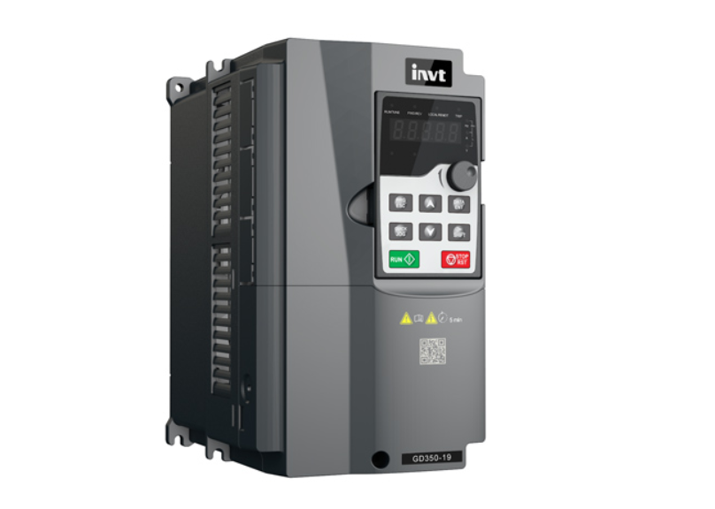
The INVT GD350-19 Series Drive is a high-performance variable frequency drive (VFD) specifically designed for crane applications.
Overview
GD350-19 series VFD is a new generation of VFD that INVT develops for cranes by using advanced control technologies based on more than ten-year accumulative crane-industry experience. The VFD has integrated rich lifting industry delicated control functions and STO fucntions, and can be widely applied to various cranes in different fields such as ports, factories, construction sites, and mining, with excellent control performance, comprehensive safety protection functions, and flexible expansion capability.
Power range:
AC 380V (-15%)–440V (+10%) 1.5–500kW
AC 520V (-15%)–690V (+10%) 22–630kW
Features
- Great torque at low frequency: 0Hz/200% (of rated torque) in feedback vector control (FVC) mode; 0.5Hz/150% (of rated torque) in space voltage vector control mode
- Excellent load adaptability: With optimized control algorithms for crane applications, the output torque can be adaptive according to the load condition so as to help achieve excellent comfortability regardless of with load or without load.
- Tower crane slewing without vortex: Helps to implement vortex removal control, with the support for quick stop in reverse braking, quick FWD/REV switchover, and low-speed jogging positioning.
- Conical rotor motor control: Helps adjust the magnetic flux according to the characteristics of conical rotor motor to realize fast brake release and closing control, simplify the commissioning steps, and ensure equipment safety.
- Special-purpose braking logic: Integrates with torque verification to achieve safe run without slip after torque establishment; supports starting direction selection and brake selection in FWD/REV switchover to meet various starting requirements flexibly.
- Travel limit protection: Includes Up/Down position limit and Up/Down DEC position limit to restrict the crane to run within the specified range. In addition to ensuring safety, this function can also optimize the stop method to improve device efficiency.
- Anti-sway protection: Uses the sensorless anti-sway control algorithm to implement anti-sway control for various cranes. It is easy to commission and flexibly adaptive.
- Loose rope protection: Avoids high-speed lifting, speed-boost malfunction, and safety accidents in loose rope state.
- Smooth lifting: Restricts the high speed at the moment of steel rope straightening in high-speed lifting mode to reduce the impact caused by the sudden load to the crane at the lifting start.
- Zero servo: Locks the motor at zero speed. That is, the motor can remain locked at zero speed even with external force applied in FWD/REV direction. Even if the brake fails, it can also drive the motor to suspend with full load or lower the load at low speed to ensure the safety of use.
- Light load speed boost: Supports the constant power and stepped speed limit modes. It can match the optimum running speed according to the actual load to reduce the crane running period and improve efficiency.
- Anti-snag protection: Indicates that the VFD outputs reserve torque so that the motor can stop at the fastest speed. This can effectively prevent the spreader from punching the top or snagging to ensure the safety.13. STO/SIL2: Cuts off torque output when the motor stops to avoid exceptional startup, which makes the running more reliable and safe. In addition, the VFD can monitor system status only if it is powered on; and it can quickly recover.
- Measuring load heights: Integrates with the rolling diameter calculation function to output the hook height information and instruct the crane driver to reduce the speed. This prevents the hook to collide with the drum.
- Master/slave control: Supports power balance and speed synchronization between the master and slave. In power balance mode, it can ensure balanced motor output to meet the rigid connection requirements for multiple motors to drive the same load. In speed synchronization mode, it can ensure that the lifting mechanism synchronization, to ensure safety. In addition, it supports a master and multiple slaves to achieve flexible master/slave switchover.
- Application macros special for cranes: Enable you to set parameters easily. Additionally, application macros can be user defined. For details about application macro parameters, see the operation manual.
- Switchover between three motors: Achieves application macro switchover simultaneously. Therefore, you do not need to set certain function parameters after the switchover. Furthermore, application macro switchover can be implemented even in master/slave mode switchover.
- Positioning stop: Supports positioning stop control for the trolley, long travel, and lifting mechanisms in closed-loop mode. This achieves more accurate equipment operating with higher efficiency.
- Open/closed loop switchover through one key: Implements the quick switchover from closed-loop control to open-loop control when the encoder is faulty. In addition, the application macro is switched accordingly. This ensures the normal running. (There is no switchover response in running state.)
- Multiple operating modes: Include operating lever, graded operating lever, electric potentiometer, communication, remote control, graded remote control and other speed giving methods to meet the application requirements of various cranes.
- Extensive add-ons: Up to three expansion cards (IO card, communication card, and PG card) supported to meet different solution applications (two expansion cards are supported for 5.5kW and lower models).
Specifications
Below table show INVT GD350-19 series drive specifications:
| Description | Specifications | |
| Power input | Input voltage (V) | AC 3PH 380V (-15%)–440V (+10%) Rated voltage: 380V AC 3PH 520V (-15%)–690V (+10%) Rated voltage: 660V |
| Input current (A) | For details, see “Product ratings”. | |
| Input frequency (Hz) | 50Hz or 60Hz; Allowed range: 47–63Hz | |
| Input power factor | ≥0.9 for 30–110kW | |
| Power output | Output voltage (V) | 0–Input voltage (V) |
| Output current (A) | For details, see “Product ratings”. | |
| Output power (kW) | For details, see “Product ratings”. | |
| Output frequency (Hz) | 0–150Hz | |
| Technical control performance | Control mode | Space voltage vector control Sensorless vector control (SVC) Feedback vector control (FVC) |
| Motor type | Asynchronous motor and permanent magnetic synchronous motor | |
| Speed ratio | 1:200 (SVC) 1:1000 (FVC) | |
| Speed control accuracy | ± 0.2% (SVC) ± 0.02% (FVC) | |
| Speed fluctuation | ± 0.3% (SVC) ± 0.02% (FVC) | |
| Torque response | < 20ms (SVC) < 10ms (FVC) | |
| Torque control accuracy | 10% (SVC) 5% (FVC) | |
| Starting torque | For asynchronous motors: 0.25Hz/150% (SVC) For synchronous motors: 2.5Hz/150% (SVC) 0Hz/200% (FVC) | |
| Overload capacity | 150% for 1 minute, 180% for 10 seconds, and 200% for 1 second | |
| Braking capability | 100% for long time, 120% for 1 minute, and 170% for 10 seconds | |
| Running control performance | Frequency setting method | Settings can be implemented through digital, analog, pulse frequency, multi-step speed running, simple PLC, PID, Modbus communication, PROFIBUS communication and so on. Settings can be combined and the setting channels can be switched. |
| Automatic voltage regulation | The output voltage can be kept constant although the grid voltage changes. | |
| Fault protection | More than 30 protection functions, such as protection against overcurrent, overvoltage, undervoltage, overtemperature, phase loss, and overload. | |
| Peripheral interface | Terminal analog input resolution | No more than 20mV |
| Terminal digital input resolution | No more than 2ms | |
| Analog input | Two inputs; AI1: 0–10V/0–20mA; AI2: -10–10V | |
| Analog output | One input; AO1: 0–10V/0–20mA | |
| Digital input | Four regular inputs; max. frequency: 1kHz; internal impedance: 3.3kΩ Two high-speed inputs; max. frequency: 50kHz; supporting quadrature encoder input; with speed measurement function | |
| Digital output | One high-speed pulse output; max. frequency: 50kHz One Y terminal open collector output | |
| Relay output | Two programmable relay outputs RO1A: NO; RO1B: NC; RO1C: common RO2A: NO; RO2B: NC; RO2C: common Contact capacity: 3A/250VAC, 1A/30VDC | |
| Extended interfaces | Three extended interfaces: SLOT1, SLOT2, and SLOT3 Supporting PG cards, programmable cards, communication cards, I/O cards and so on Note: 1. You can install optional expansion cards for 1.5–5.5kW VFD models and you are recommended to install them at slot 2. 2. I/O expansion card 2 has been installed at slot 3 for 7.5kW and higher VFD models as standard configuration. | |
| I/O expansion card 2 | Relay output | Two programmable relay outputs. Contact capacity: 3A/250VAC, 1A/30VDC RO3A: NO; RO3C: common; RO4A: NO; RO4C: common |
| Digital input | Four regular inputs; supporting PTC input only with DC power supply, while PTC acts at 2.5kΩInternal impedance: 6.6kΩ Max. input frequency: 1kHz Supporting internal power 24V Supporting the voltage input of external power (-20%)24–48VDC(+10%) and (-10%)24–48VAC(+10%) Bidirectional input terminals, simultaneously supporting NPN and PNP connection methods | |
| PT100 input | Independent PT100 and PT1000 input: 1. Resolution: 1°C 2. Range: -20°C–+150°C 3. Detection accuracy: ±3°C 4. Supporting offline protection | |
| PT1000 input | ||
| Other | Installation method | Supports wall-mounting, floor-mounting and flange-mounting. |
| Temperature of running environment | -10°C–+50°C. Derating is required when the temperature exceeds 40°C. | |
| IP rating | IP20 | |
| Pollution degree | Degree 2 | |
| Cooling method | Forced air cooling | |
| DC reactor | Standard built-in part for 380V 18.5–110kW VFD models. Optional external part for 380V 132kW and higher models and for 660V models. | |
| Braking unit | Standard built-in part for 380V 110kW and lower VFD models. Optional external part for 660V models. | |
| EMC filter | Supporting built-in C3 filters (optional). If a C3 filter is required, connect the jumper J10. After a C3 filter is configured, the VFD can meet IEC61800-3 C3 requirements.Supporting external filters (optional). After an external filter is configured, the VFD can meet IEC61800-3 C2 requirements. | |