Nidec Control Techniques F600 Pump Drive – Find comprehensive resources for Nidec & Control Technique F600 Pump AC drives, including product catalogs, manuals, price list, programming guides, fault, alarm, warnings & software support. Get expert assistance for troubleshooting and optimization.
Nidec Control Techniques F600 is a specialized AC drive designed specifically for pump applications. It’s part of their “Specialist” series, focusing on industry-specific needs.
Features
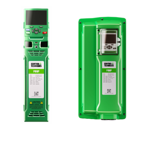
Applications involving the flow of water demand extreme reliability and low energy consumption. Available in IP20 and IP65 packages, Control Techniques’ F600 drive, part of the newly introduced Specialist series of industry-specific drive technologies, builds on our company’s five decades of drives expertise, delivering precise, dependable flow control.
Unmatched total cost of ownership, with innovative protective features and extended equipment life
The F600 has comprehensive pump and motor protection features which minimise unplanned downtime, improving overall effectiveness and guaranteeing better value for money. Bring true resilience to your application and easily ride-through component failures.
Automatic error recovery
In the unlikely event of detecting an error with your pump, the F600 has the ability to dynamically recover and resume normal operation.
Limit protection
If the feedback exceeds the limits defined for your application, the F600 has the ability to raise an alarm or stop the drive to protect your equipment and preserve its lifetime.
Transducer loss protection
In the event of losing connection to the transducer, the F600 can stop, continue to run at a fixed speed or ignore the fault depending on the application requirements.
Fire mode
Fire mode allows the drive to disable all trips and to continue to run uninterrupted during emergency events if the application requires.
Save on energy through a wide range of energy features
The F600 is 98% efficient, meaning very little energy is lost in power conversion.
Even more, the real savings potential gets unlocked by the F600’s built-in features that can further reduce energy consumption:
Low load savings
The F600 helps maximise energy savings when demand is low. Activing Control Techniques’ leading-edge Low Load Power Saving function, the drive dynamically reduces the voltage applied to reduce losses in the motor and make the system more efficient.
The F600 features optimised control for your flow applications
Pipe fill
Prevent spikes in pressure at start-up using a controlled ramp, to protect your piping system and the pump itself.
Dry-run prevention
Prevent the pump running dry by checking the load against a threshold; with flexible configurations to dynamically adjust output, set an alarm or stop the drive.
Over-cycling protection
Optimise drive, motor and pump sizing, and regulate pump wear by limiting the number of start-stops per hour. Flexible configurations allow to dynamically alter cycling reference limits, set an alarm or stop the drive when a limit is reached.
No-flow detection
Where there is no-flow or low-flow, the F600 drive can automatically enter sleep mode to save energy, based on the feedback of a pulsed flow transducer, or triggered by a flow switch, or detected by the software alone.
Cleaning
Live, continuous monitoring of the system is used to trigger an automatic drive-based cleansing cycle to clear the pump impeller and help avoid maintenance costs on cleaning pump blockages.
Level switch control
Level switches provide critical protection for tanks in the event of the level reaching a “high” switch, whereby the pump is stopped, or a “low” switch, whereby the pump is started, to ensure pumping within tank levels.
Pump control modes | flexible support for every system
Single pump
Control Techniques’ Single Pump mode is an effective and versatile variable speed control solution for maintaining a constant set-point in a single pump configuration.
- Fire mode allows the drive to disable all trips and to continue to run uninterrupted during emergency events if the application requires
Cascade
Cascade mode allows the F600 to operate with up to 4 assist pumps to aid the primary pump when required.
- Energy usage is optimised whereby the assist pumps are only enabled when demand reaches sufficient levels.
- Assist pumps are used alternately to apply uniform wear and increase pump availability.
- Over-cycling protection for assist pumps to control the number of starts and stops per hour.
Multi-leader
Complete control of your application with up to 3 x F600 drives and maximum energy savings with these variable frequency drives running parallel.
- The Multi-leader drive configuration provides redundancy and removes the need for a PLC
- The “lead” drive is automatically cycled to apply uniform wear
- If the “lead” drive loses its transducer, it can access the transducer feedback from another F600 in the system over Ethernet
- Dynamic re-selection of “lead” pump if a pump is taken out of service or develops a fault
Pump Drive F600 ratings guide
200/240 Vac ±10%
| Drive | Normal Duty | ||
| Max continuous current (A) | Motor shaft power (kW) | Motor shaft power (hp) | |
| F600-03200066A10 | 6.6 | 1.1 | 1.5 |
| F600-03200080A10 | 8 | 1.5 | 2 |
| F600-03200110A10 | 11 | 2.2 | 3 |
| F600-03200127A10 | 12.7 | 3 | 3 |
| F600-04200180A10 | 18 | 4 | 5 |
| F600-04200250A10 | 25 | 5.5 | 7.5 |
| F600-05200300A10 | 30 | 7.5 | 10 |
| F600-06200500A10 | 50 | 11 | 15 |
| F600-06200580A10 | 58 | 15 | 20 |
| F600-07200750A10 | 75 | 18.5 | 25 |
| F600-07200940A10 | 94 | 22 | 30 |
| F600-07201170A10 | 117 | 30 | 40 |
| F600-08201490A10 | 149 | 37 | 50 |
| F600-08201800A10 | 180 | 45 | 60 |
| F600-09202160A10 | 216 | 55 | 75 |
| F600-09202660A10 | 266 | 75 | 100 |
| F600-09202160E10 | 216 | 55 | 75 |
| F600-09202660E10 | 266 | 75 | 100 |
| F600-10203250E10 | 325 | 90 | 125 |
| F600-10203600E10 | 360 | 110 | 150 |
380/480 Vac ±10%
| Drive | Normal Duty | ||
| Max continuous current (A) | Motor shaft power (kW) | Motor shaft power (hp) | |
| F600-03400034A10 | 3.4 | 1.1 | 1.5 |
| F600-03400045A10 | 4.5 | 1.5 | 2 |
| F600-03400062A10 | 6.2 | 2.2 | 3 |
| F600-03400077A10 | 7.7 | 3 | 5 |
| F600-03400104A10 | 10.4 | 4 | 5 |
| F600-03400123A10 | 12.3 | 5.5 | 7.5 |
| F600-04400185A10 | 18.5 | 7.5 | 10 |
| F600-04400240A10 | 24 | 11 | 15 |
| F600-05400300A10 | 30 | 15 | 20 |
| F600-06400380A10 | 38 | 18.5 | 25 |
| F600-06400480A10 | 48 | 22 | 30 |
| F600-06400630A10 | 63 | 30 | 40 |
| F600-07400790A10 | 79 | 37 | 50 |
| F600-07400940A10 | 94 | 45 | 60 |
| F600-07401120A10 | 112 | 55 | 75 |
| F600-08401550A10 | 155 | 75 | 100 |
| F600-08401840A10 | 184 | 90 | 125 |
| F600-09402210A10 | 221 | 110 | 150 |
| F600-09402660A10 | 266 | 132 | 200 |
| F600-09402210E10 | 221 | 110 | 150 |
| F600-09402660E10 | 266 | 132 | 200 |
| F600-10403200E10 | 320 | 160 | 250 |
| F600-10403610E10 | 361 | 200 | 300 |
| F600-11404370E10 | 437 | 225 | 350 |
| F600-11404870E10 | 487 | 250 | 400 |
| F600-11405070E10 | 507 | 280 | 450 |
| F600-12404800TU0 | 608 | 315 | 500 |
| F600-12405660TU0 | 660 | 355 | 550 |
| F600-12406600TU0 | 755 | 400 | 650 |
| F600-12407200TU0 | 8651 | 500 | 700 |
Note1: 110 % Overload at 30˚C and below and No Overload above that.
500/575 Vac ±10%
| Drive | Normal Duty | ||
| Max continuous current (A) | Motor shaft power (kW) | Motor shaft power (hp) | |
| F600-05500039A10 | 3.9 | 2.2 | 3 |
| F600-05500061A10 | 6.1 | 4 | 5 |
| F600-05500100A10 | 10 | 5.5 | 7.5 |
| F600-06500120A10 | 12 | 7.5 | 10 |
| F600-06500170A10 | 17 | 11 | 15 |
| F600-06500220A10 | 22 | 15 | 20 |
| F600-06500270A10 | 27 | 18.5 | 25 |
| F600-06500340A10 | 34 | 22 | 30 |
| F600-06500430A10 | 43 | 30 | 40 |
| F600-07500530A10 | 53 | 37 | 50 |
| F600-07500730A10 | 73 | 45 | 60 |
| F600-08500860A10 | 86 | 55 | 75 |
| F600-08501080A10 | 108 | 75 | 100 |
| F600-09501250A10 | 125 | 90 | 125 |
| F600-09501550A10 | 155 | 110 | 150 |
| F600-09501250E10 | 125 | 90 | 125 |
| F600-09501500E10 | 150 | 110 | 150 |
| F600-10502000E10 | 200 | 130 | 200 |
| F600-11502480E10 | 248 | 175 | 250 |
| F600-11502880E10 | 288 | 225 | 300 |
| F600-11503150E10 | 315 | 250 | 350 |
| F600-12503150 | 376 | 250 | 350 |
| F600-12503600 | 428 | 300 | 400 |
| F600-12504100 | 480 | 330 | 450 |
| F600-12504600 | 532 | 370 | 500 |
500/690 Vac ±10%
| Drive | Normal Duty | ||
| Max continuous current (A) | Motor shaft power (kW) | Motor shaft power (hp) | |
| F600-07600230A10 | 23 | 18.5 | 25 |
| F600-07600300A10 | 30 | 22 | 30 |
| F600-07600360A10 | 36 | 30 | 40 |
| F600-07600460A10 | 46 | 37 | 50 |
| F600-07600520A10 | 52 | 45 | 60 |
| F600-07600730A10 | 73 | 55 | 75 |
| F600-08600860A10 | 86 | 75 | 100 |
| F600-08601080A10 | 108 | 90 | 125 |
| F600-09601250A10 | 125 | 110 | 150 |
| F600-09601500A10 | 150 | 132 | 175 |
| F600-09601250E10 | 125 | 110 | 150 |
| F600-09601550E10 | 155 | 132 | 175 |
| F600-10601720E10 | 172 | 160 | 200 |
| F600-10601970E10 | 197 | 185 | 250 |
| F600-11602250E10 | 225 | 200 | 250 |
| F600-11602750E10 | 275 | 250 | 300 |
| F600-11603050E10 | 305 | 280 | 400 |
| F600-12603150 | 376 | 355 | 450 |
| F600-12603600 | 428 | 400 | 500 |
| F600-12604100 | 480 | 450 | 600 |
| F600-12604600 | 532 | 500 | 650 |
Normal duty operation only
Suitable for pump applications, with a current overload requirement of 110% for 60 s*.
Conformance
- IP20 / NEMA1 / UL TYPE 1 *UL open class as standard, additional kit needed to achieve Type 1
- IP65 / NEMA4 / UL TYPE 12 rating is achieved on the rear of the drive when through panel mounted
- *Frame size 9D, 9E, 10D and 10E achieve IP55 / NEMA 4 / UL Type 12
- Ambient temperature -20 °C to 40 °C (-4 °F to 104 °F) as standard. Up to 55 °C (131 °F) with derating
- Humidity 95 % maximum (non-condensing) at 40 °C (104 °F)
- Altitude: 0 to 3000 m (9900 ft), derate 1 % per 100 m (330 ft) between 1000 m (3300 ft) and 3000 m (9900 ft)
- Random Vibration Tested in accordance with IEC 60068-2-64
- Bump Tested in accordance with IEC 60068-2-29
- Sinusoidal Vibration Tested in accordance with IEC 60068-2-6
- Mechanical Shock Tested in accordance with IEC 60068-2-29
- Storage temperature -40 °C to 55 °C (-40 °F to 131 °F) or up to 70 °C (158 °F) for short-term storage
- Electromagnetic Immunity complies with EN 61800-3 and EN 61000-6-2
- With onboard EMC filter, emissions comply with EN 61800-3 (category C3)
- EN 61000-6-3 and EN 61000-6-4 with optional footprint EMC filter
- IEC 60146-1-1 Supply conditions (category C1 or C2 depending on rating)
- IEC 61800-5-1 (Electrical Safety)
- IEC 61131-2 I/O
- EN 61000-3-12 with optional line reactor
- UL 508C (Electrical Safety)
Dimensions
| Frame size | Dimensions | Weight | |
| mm (HxWxD) | in (HxWxD) | kg (lb) | |
| 3 | 382 x 83 x 200 | 15.0 x 3.3 x 7.9 | 4.5 (9.9) |
| 4 | 391 x 124 x 200 | 15.4 x 4.9 x 7.9 | 6.5 (14.3) |
| 5 | 391 x 143 x 200 | 15.4 x 5.6 x 7.6 | 7.4 (16.3) |
| 6 | 391 x 210 x 227 | 15.4 x 8.3 x 8.9 | 14 (30.9) |
| 7 | 557 x 270 x 280 | 21.9 x 10.6 x 11.0 | 28 (61.7) |
| 8 | 803 x 310 x 290 | 31.6 x 12.2 x 11.4 | 50 (110.2) |
| 9A | 1108 x 310 x 290 | 43.6 x 12.2 x 11.4 | 66.5 (146.6) |
| 9E/10E | 1069 x 310 x 290 | 42.1 x 12.2 x 11.4 | 46 (101.4) |
| 9D/10D | Rectifier 355 x 310 x 290 ——————— Inverter 773 x 310 x 290 | Rectifier 15.8 x 12.2 x 11.4 ———————– Inverter 30.4 x 12.2 x 11.4 | |
| 11E | 1242 x 310 x 312 | 48.9 x 12.2 x 12.3 | 63 (138.9) |
| 12 | 1750 x 295 x 526 | 68.9 x 11.6 x 20.7 | AC to AC (‘T’ type): 130 kg (287 lb) DC to AC (‘D’ type): 113 kg (249 lb) |
*For more detailed information please see technical documents.