Toshiba Q9+ Plus Drive – Find comprehensive resources for Toshiba Q9+ Plus AC drive, including product catalogs, manuals, price list, programming guides, fault, alarm, warnings & software support. Get expert assistance for troubleshooting and optimization.
Toshiba Q9+ Plus Drive is a sophisticated adjustable speed drive (ASD) primarily designed for HVAC applications, with a strong emphasis on precise pump control.
Features
The Toshiba Q9 Plus adjustable speed drive is a revolution in pump control. By incorporating Toshiba’s proprietary, ground-breaking Virtual Linear Pump (VLP) Technology®, the Q9 Plus directly, precisely, and linearly controls pressure, level, or flow. This eliminates many obstacles users thought were an integral part of pump control and sets a new standard in ingenuity, performance, and ease-of-use for the pump industry.
Features:
- Linearizes Traditional Non-Linear Fan Curve, Providing Stable & Precise Control to HVAC Systems
- Solves Problem of Load-Balancing Over Multiple Fan Plenums or Pump Systems
- Allows User to Configure System in Five Simple Steps, Providing Complete Control in Only Minutes
- Self-Calibrates & Eliminates Common Anomalies
- Maximizes Energy Savings on Variable Torque Loads
The Q9 Plus supports many common communication protocols used in the HVAC industry.
- Modbus RTU (Integrated)
- BACnet ® (Integrated)
Toshiba Q9+ Plus Drive is designed to provide highly accurate and efficient control for HVAC pumping and fan applications, with a particular focus on simplifying pump system management.
Specifications
| MODEL RANGE | 1 to 125 HP | 1 to 400 HP |
| Voltage Rating | 200 to 240 VAC | 380 to 480 VAC |
| Frame Size | 2 to 10 | 2 to 13 |
| HP Rating | 1 to 125 HP | 1 to 400 HP |
| Input Voltage Tolerance | +- 10% | |
| Voltage Regulation | Main Circuit Voltage Feedback Control: Automatic, Fixed, & Off | |
| PWM Carrier Frequency Control System | Adjustable 1 to 16 kHz (Drive-Specific, Consult Factory) | |
| Sinusoidal Pulse Width Modulation (PWM) with VLP Technology® | ||
| V/f Pattern | Constant Torque, Voltage Decrease Curve, Automatic Torque Boost, Sensorless Vector Control, 5-Point V/f Custom Curve, PM Drive & PG Feedback Vector Control | |
| Overload Current Rating | 100% Continuous; 110% for One Minute | |
| Frequency Setting | Rotary Encoder Integrated into EOI, 0 to 10 VDC, ±10 VDC, 0 to 20 mA & Discrete Input | |
| Frequency Precision | Analog Input 0.2% of Maximum Output Frequency; Discrete/Communications Input 0.01% of Maximum Output Frequency | |
| Output Frequency Range | 0 to 299 Hz | |
| Speed Regulation | Closed Loop (Up to 0.01%; 1000:1 Speed Range); Open Loop (Up to 0.1%; 60:1 Speed Range) | |
| Set Point Control Load Balancing | Selectable Between VLP Technology/PID; Proportional Gain, Integral Gain, Feedback Settings, Upper/Lower Deviation Limits, Feedback Source Delay Filter & Feedback Settings Differential Gain | |
| Capable of Balancing Load on Pumps Operated by Q9 Plus Drives on Common Header | ||
| Retry | User-Set Number of Retries for Automatic System Restart After Trip | |
| Restart Sleep Timer | Able to Smoothly Catch Freewheeling Motor (Bidirectional) | |
| Shuts Off Fan After Running at Minimum for User-Specified Time | ||
| Enclosure Type | IP20/IP00 (Rating-Dependent), NEMA 1 Kit Available | |
| Standards/Compliances | UL Listed | |
| INPUT/OUTPUT | ||
| Discrete Input Terminals | Eight Discrete Input Terminals Programmable to 57 Functions; May Be Increased Using Optional Hardware | |
| Analog Inputs | Three: One 0 to 20 mA or 0 to 10 VDC Isolated Input, One 0 To 10 VDC Input & One ±10 VDC Input | |
| Discrete Output Contacts Analog Outputs | Three Programmable To 83 Functions; Two Form-A Contacts & One Form-C Contact | |
| Two: One Programmable 4 to 20 mA or 0 to 10 VDC & One 4 to 20 mA Output | ||
| Communication Port | Half/Full Duplex RS485; Integrated Protocols: BACnet®, Modbus®, & Toshiba TSB | |
| Power Terminals | Input (L1, L2, L3), Output (T1, T2, T3), DCL (PO, PA), DBR (PA, PB) & DC BUS (PA, PC) | |
| SAFETY FEATURES | ||
| Start & Stop Points | Determine Start/Stop Based On User-Set Values, Transducer Feedback Signal & Programmable Discrete Input Terminal; Work with Delay Timer to Help Ensure ASD Does Not Start/Stop Too Frequently Due to Unstable/Fluctuating Input Signal | |
| Damper-Permissive Circuit | Protects Drive from Over-Pressuring the System | |
| Selectable Fire-Speeds | Two Fire-Speeds; Force Drive to Run at Preset Speeds | |
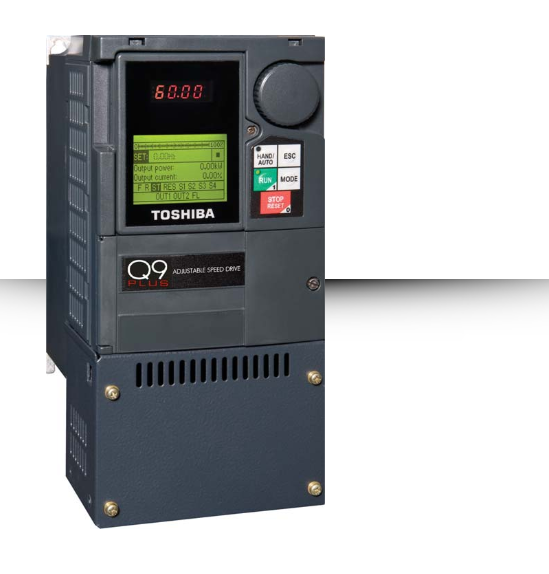
| ELECTRONIC OPERATOR INTERFACE (EOI) | ||
| LCD (Liquid Crystal Display) | Full-English Backlit Display | |
| LED (Light Emitting Diode) | Seven-Segment Display | |
| LED Indicators | Run (Red)/Stop (Green), Hand (Green) & DC Bus Charge Indicator (Red) | |
| Keys Rotary Encoder | Hand/Auto, ESC, Run, Mode & Stop/Reset | |
| Encoder with Integrated Enter Key to View/Change Parameter Settings | ||
| Monitoring | Frequency Command Screen; Allows Two User-Selected Monitored Items to be Displayed; Selectable from: Output Current, DC Voltage, Output Voltage, Run Time, Comp. Frequency, VLP Technology®, Motor Overload, Motor Load, ASD Load, Input Power, Output Power, RR Input, V/I Input, RX Input, RX2 Input, AM/FM Output | |
| Display Units | Completely Configurable Along with Scaling Factor Multiplier; Display Selectable Between Amps (A) or Percentage of FLA (%); Voltage Display Selectable Between Volts (V) or Percentage of Volts (%) | |
| Set-Point Units | Selectable Between PSI, GPM, CFM, Inches of Water Column (inH2O), or Feet of Water Column (ftWC) | |