Master the basics of a flow control loop in industrial automation. Learn about flow transmitters, PID controllers, control valves, and how they work together.
Flow Control Loop Basics: A Complete Guide to Industrial Flow Control
In the process manufacturing industry—whether it is a massive oil refinery, a water treatment plant, or a food processing facility—moving liquids and gases from one place to another is the fundamental basis of operation. But you cannot just turn on a pump and hope for the best; the rate at which these fluids move must be strictly regulated. This is achieved using a flow control loop.
But what exactly is a flow control loop, and how does it manage to keep fluid flow so perfectly stabilized? In this comprehensive guide, we will break down the flow control loop basics, explore its main components, explain how it works step-by-step, and look at the unique challenges of tuning it.
What is a Flow Control Loop?
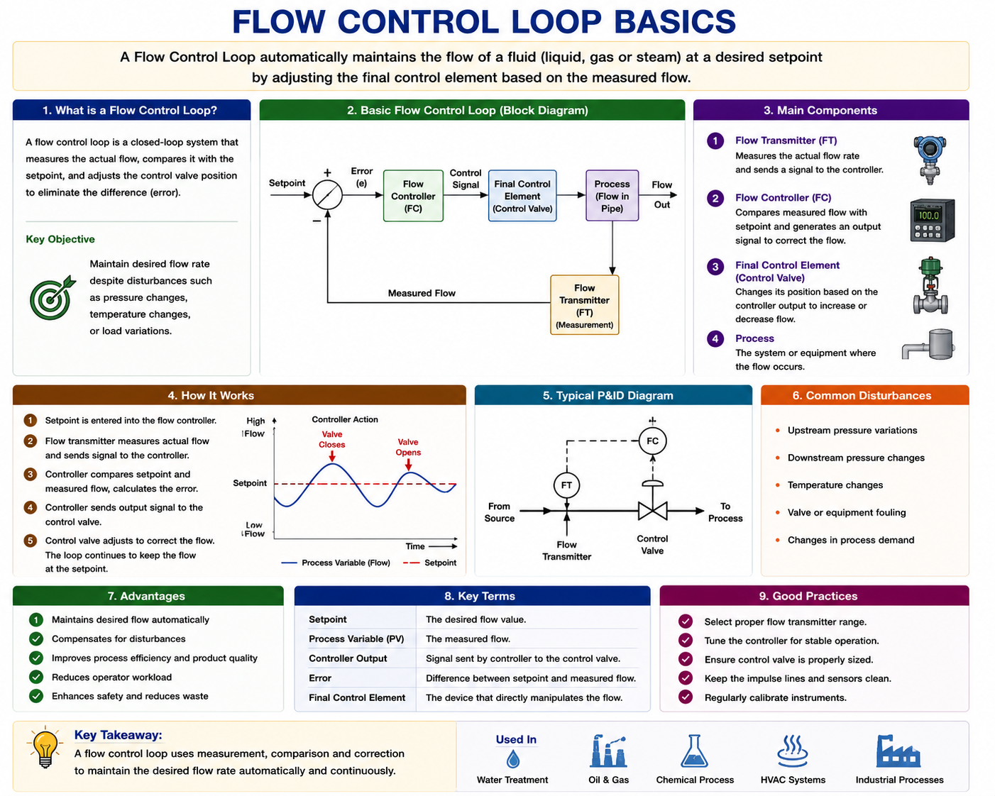
A flow control loop is a closed-loop system designed to measure, regulate, and maintain a specific flow rate of a fluid or gas within a pipe.
It continuously monitors the actual flow rate going through the pipe, compares it to a desired target flow rate set by an operator, and automatically makes adjustments to a valve or pump to correct any deviations.
The 4 Main Components of a Flow Control Loop
Every industrial flow control loop, no matter how complex the plant is, consists of four fundamental components working together in harmony:
1. The Primary Sensing Element (Flowmeter)
This is the physical device installed directly in the pipeline that detects the movement of the fluid. It acts as the “eyes” of the system. Different types of fluids require different types of sensing elements, including:
- Differential Pressure (DP) Orifice Plates: Measures the pressure drop across a restriction to calculate flow.
- Magnetic Flowmeters (Magmeters): Uses a magnetic field to measure the flow of conductive liquids.
- Coriolis Meters: Highly accurate meters that measure mass flow directly using vibrating tubes.
- Ultrasonic Meters: Uses sound waves to measure fluid velocity without physically contacting the fluid.
2. The Flow Transmitter (FT)
The primary sensor generates a raw physical signal (like a pressure difference or a tiny voltage). The transmitter takes this raw data, calculates the actual flow rate, and converts it into an electrical signal that the control system can understand (usually an analog 4-20mA signal or a digital protocol like HART, Profibus, or Foundation Fieldbus).
3. The Controller (PLC or DCS)
The controller acts as the “brain” of the loop. It is typically a PID (Proportional-Integral-Derivative) controller located within a Programmable Logic Controller (PLC) or Distributed Control System (DCS). The controller looks at two main numbers:
- Setpoint (SP): The desired flow rate requested by the operator (e.g., 500 gallons per minute).
- Process Variable (PV): The actual flow rate currently being reported by the flow transmitter.
4. The Final Control Element
This is the “muscle” of the loop. Based on the commands received from the controller, the final control element physically changes the flow of the process. The two most common final control elements are:
- Control Valves: An automated valve that modulates (opens or closes incrementally) to restrict or allow more fluid through the pipe.
- Variable Frequency Drives (VFDs): An electronic device that speeds up or slows down the electric motor driving a pump.
How a Flow Control Loop Works (The Step-by-Step Process)
To understand the basics, let’s look at how these four components interact in a continuous cycle:
- Measurement: The flow transmitter measures the current fluid flow (Process Variable) and sends this data to the controller.
- Comparison: The controller calculates the Error. (Error = Setpoint – Process Variable). For example, if the Setpoint is 100 GPM and the actual flow is 90 GPM, there is a -10 GPM error.
- Calculation: Using its internal PID algorithm, the controller determines exactly how much the valve needs to open to eliminate that 10 GPM error.
- Adjustment: The controller sends an output signal to the control valve, commanding it to open a few extra percentages.
- Repeat: The transmitter reads the new flow rate, and the cycle begins again. This happens several times a second!
The Unique Challenge: Tuning a Flow Loop
Automation engineers must “tune” the PID controller so it reacts appropriately to errors. Flow control loops are notorious for having two unique characteristics that make tuning them different from temperature or level loops:
- Extremely Fast Dynamics: Unlike a large tank of water taking hours to heat up, fluid flow changes instantly the moment a valve moves. Because of this fast response, flow loops have very little “dead time.”
- High Process Noise: Fluid moving rapidly through a pipe causes turbulence, swirls, and pressure fluctuations. This makes the flow transmitter signal look very “noisy” and jittery on a graph.
The Tuning Rule of Thumb for Flow: Because of the high noise, engineers almost never use the Derivative (D) action in a flow loop, as it would cause the valve to wildly overreact to every little turbulent spike. Instead, flow loops rely on a low Proportional (P) gain and a very fast Integral (I) action to smooth out the noise and achieve steady control.
Conclusion
Understanding flow control loop basics is essential for anyone entering the fields of instrumentation, automation, or process engineering. By mastering how transmitters, PID controllers, and control valves work together to measure, compare, and adjust fluid movement, you hold the key to keeping industrial plants running safely, efficiently, and profitably.
Frequently Asked Questions (FAQs)
What is the difference between open-loop and closed-loop flow control?
In an open-loop system, an operator manually sets a valve to 50% open and hopes the flow is correct; there is no automatic feedback. In a closed-loop system, a flowmeter continuously sends feedback to a controller, which automatically adjusts the valve to maintain the exact desired flow rate regardless of pressure changes.
Why shouldn’t I use the Derivative (D) term when tuning a flow loop?
The Derivative action reacts to the rate of change of the error. Because flow signals are inherently noisy due to fluid turbulence, the Derivative action will amplify this noise, causing the control valve to rapidly chatter, which can severely damage the valve stem and packing.
Can a flow control loop work without a control valve?
Yes! Modern process plants increasingly use Variable Frequency Drives (VFDs) on pumps as the final control element instead of control valves. Instead of wasting energy by restricting flow with a valve, the controller simply tells the pump motor to spin faster or slower to achieve the desired flow rate.