Learn how to easily set up your ABB ACS880 VFD. This step-by-step guide covers power wiring, control wiring (start/stop & speed reference), and essential parameter settings.

If you work in industrial automation, you already know that the ABB ACS880 is an absolute powerhouse. Built on ABB’s premium Direct Torque Control (DTC) technology, this all-compatible industrial drive can handle almost any motor-driven application you throw at it. But with great power comes a massive parameter list—which can feel a bit overwhelming if you’re setting it up for the first time.
Don’t worry! In this guide, we are going to break down the setup process into simple, bite-sized steps. We’ll walk through the power wiring, the control wiring for your basic start/stop and speed references, and exactly which parameters you need to tweak to get your motor spinning safely and efficiently.
Let’s dive right in!
Step 1: Power Wiring (Input & Output)
Safety First: Before opening the drive cover, ensure that all power sources are isolated, locked out, and tagged out. Wait at least 5 minutes for the internal DC link capacitors to discharge before touching any terminals.
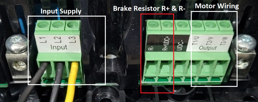
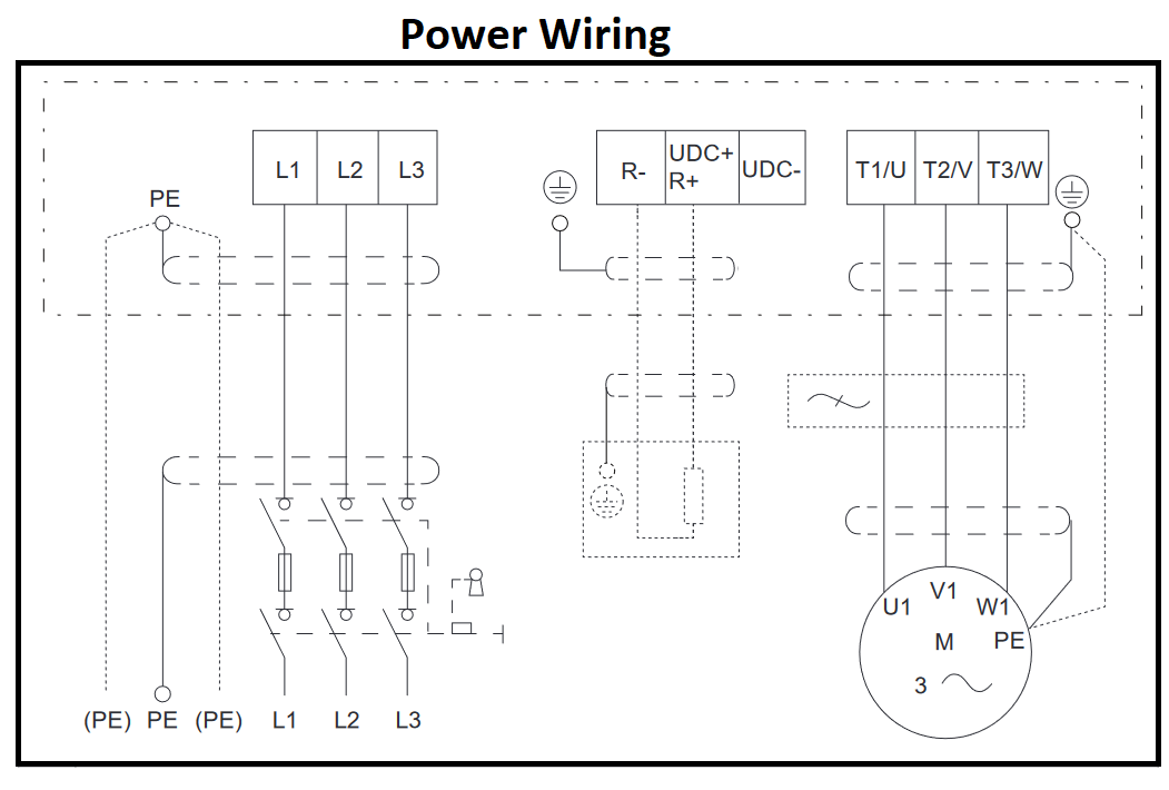
Power wiring on the ACS880 is straightforward, but it’s crucial to get it right to prevent damage to the drive or motor.
- Input Power (From the Grid): Connect your 3-phase incoming power supply to the terminals marked L1, L2, and L3 (sometimes marked U1, V1, W1 depending on the frame size).
- Output Power (To the Motor): Connect your motor cables to the terminals marked T1/U2, T2/V2, and T3/W2.
- Grounding (PE): Never skip the ground! Connect the protective earth cable from the main supply to the drive’s PE terminal, and run another ground cable from the drive’s PE terminal to the motor frame. Proper grounding is essential for safety and minimizing electrical noise.
Pro Tip: Always use symmetrical shielded cables for the motor output. This prevents electromagnetic interference (EMI) from messing with your control signals or nearby sensitive equipment.
Step 2: Control Wiring (Start/Stop & Speed Reference)
Now that we have power, we need to tell the drive when to run and how fast to go. We’ll wire this up using the ACS880’s default “Factory Macro,” which is perfect for standard I/O control.
Start/Stop Control Wiring (Digital Inputs)
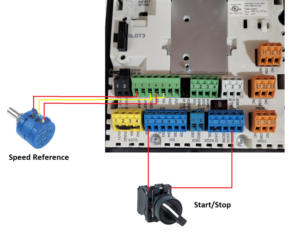
To start and stop the drive using an external switch or PLC relay, we use the Digital Inputs (DI). In the factory default setting, DI1 is assigned to the Start/Stop command.
- Connect a wire from the +24V DC terminal (usually Terminal 10 on the XPOW/XD24 block) to one side of your normally open (NO) start switch.
- Connect the other side of your switch to DI1 (Terminal 13 on the XDI block).
- How it works: When you close the switch, 24V hits DI1, and the drive starts. Open the switch, and the drive stops.
Speed Reference Wiring (Analog Inputs)
To control the speed using an external potentiometer or a PLC (0-10V signal), we use the Analog Inputs (AI). By default, AI1 handles the external speed reference.
- If using a 10k Ohm Potentiometer:
- Connect the wiper (middle pin) to AI1+ (Terminal 4).
- Connect the positive end of the pot to the drive’s +10V reference (Terminal 2).
- Connect the negative end of the pot to AGND (Analog Ground, Terminal 3).
- If using a 0-10V PLC signal: Connect the positive signal wire to AI1+ (Terminal 4) and the negative to AI1- / AGND (Terminal 5).
Step 3: ACS880 Parameter Setting
With the physical wiring done, it’s time to program the brain of the ACS880. Grab your control panel (keypad) and navigate to the Parameters menu. Here are the essential groups you need to set up.
1. Motor Data (Group 99)
You need your motor’s nameplate for this part. The drive must know exactly what kind of motor it is running to optimize the Direct Torque Control.
- 99.03 Motor Type: Select your motor type (e.g., Asynchronous motor, Permanent magnet motor).
- 99.04 Motor Control Mode: Set to DTC (Direct Torque Control) for high performance, or Scalar if you are running multiple motors on one drive or testing without a motor attached.
- 99.06 Motor Nominal Current: Enter the Amps from the motor nameplate.
- 99.07 Motor Nominal Voltage: Enter the Voltage from the nameplate.
- 99.08 Motor Nominal Frequency: Enter the Hz (usually 50Hz or 60Hz).
- 99.09 Motor Nominal Speed: Enter the RPM from the nameplate.
- 99.10 Motor Nominal Power: Enter the kW or HP rating.
2. Start/Stop Command Configuration (Group 20)
Let’s confirm the drive is looking at our DI1 switch for the start command.
- 20.01 Ext1 Commands: Set this to In1 Start. This tells the drive that Digital Input 1 (DI1) acts as the run/stop signal.
3. Speed Reference Configuration (Group 22)
Now, let’s tell the drive to listen to our potentiometer/PLC for the speed command.
- 22.11 Ext1 Speed Ref1: Set this to AI1 scaled. This routes the analog input we wired earlier to the main speed controller.
4. Application Limits (Group 30)
Setting proper limits protects your mechanical equipment and the motor.
- 30.11 Minimum Speed: Set the lowest allowed running speed (e.g., 0 rpm).
- 30.12 Maximum Speed: Set the highest allowed safe speed (e.g., 1500 rpm).
- 30.17 Maximum Current: Set this to protect the motor from overloads (usually set slightly above nominal current, depending on the application).
5. Acceleration and Deceleration Ramps (Group 23)
You don’t want your motor snapping to full speed instantly (unless your process requires it). Ramping saves mechanical wear and tear.
- 23.12 Acceleration Time 1: Time required to go from zero to maximum speed (e.g., 5.0 seconds).
- 23.13 Deceleration Time 1: Time required to coast/brake from maximum speed to zero (e.g., 5.0 seconds).
Ready to Run!
Once you’ve input the motor data and set up your control wiring parameters, perform a quick Motor ID Run (Parameter 99.13). The drive will pass a current through the motor to map its electrical characteristics, ensuring you get the absolute best performance possible.
And there you have it! You have successfully wired the power, configured the start/stop and speed controls, and programmed the essential parameters on your ABB ACS880 drive. Switch your control panel to “Auto/Remote” mode, flip your start switch, turn your speed dial, and watch your motor run smoothly.