Getting the ABB ACS550 A2010 Motor Temp alarm? Learn how to diagnose motor overheating, check thermal feedback sensors, and adjust Group 35 parameters to prevent an unexpected trip.
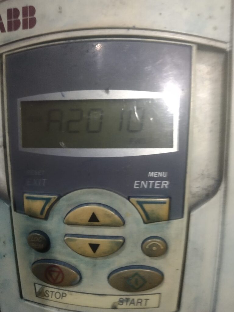
If your ABB ACS550 drive starts displaying Warning A2010, your drive is issuing a serious “yellow light” warning: Motor Temperature is too high.
The ACS550 is constantly calculating the thermal state of your motor. This alarm means your motor is approaching a dangerous heat level. If the temperature continues to rise, the drive will eventually trigger an MOT OVERTEMP fault trip, which will stop your process entirely. Here is how to investigate and fix the root cause.
Why is the A2010 Alarm Triggering?
The ACS550 determines motor temperature in two ways: via an internal mathematical model (based on drive parameters) or via an external sensor (like a PTC thermistor). The alarm is caused by one of these two methods detecting excessive heat.
Step-by-Step Troubleshooting
1. Check for Real Overload
Before changing any settings, verify if the motor is actually hot to the touch:
- Mechanical Load: Is the driven machine (pump, fan, conveyor) jammed, seized, or running at a load higher than the motor’s rated power?
- Cooling System: Is the motor fan covered in dust, or is the environment temperature too high? A motor running in a hot room with clogged cooling fins will overheat quickly.
- Motor Current: Check the actual current being drawn (Monitor Parameter 0103). If it is consistently higher than the motor’s nominal current (9906), the motor is overloaded.
2. Verify Group 35: Motor Temp Measurement
If the motor feels cool but the alarm persists, your feedback sensor might be faulty:
- If you are using a temperature sensor (PTC/KTY), check Group 35 (MOTOR TEMP MEAS).
- Ensure your settings in 3501 (SENSOR TYPE) match the hardware installed in the motor.
- A loose wire or a faulty sensor lead can cause the drive to report a “fake” high-temperature reading. Check the resistance between the sensor leads at the drive terminal block.
3. Adjust the Motor Thermal Model (Groups 3005–3009)
If you are not using an external sensor, the drive uses a built-in mathematical model. If this model is misconfigured, it will report “Overheat” even if the motor is healthy.
- 3005 (MOT THERM PROT): Ensure this is set correctly for your application.
- 3006 (MOT THERM TIME): This sets the time constant for the motor’s heating model. If the value is too small, the drive will react too quickly to short-term current spikes.
- 3007 (MOT LOAD CURVE): Verify that this curve accurately reflects the motor’s ability to dissipate heat, especially if the motor is running at low speeds (where internal fans are less effective).
Quick Summary Checklist
| Checklist Item | Action |
|---|---|
| Motor Load | Measure current; check for mechanical binding. |
| Cooling | Clean motor cooling fins and air intakes. |
| Sensor Feedback | Verify wiring and resistance of the thermistor (Group 35). |
| Thermal Model | Confirm 3005-3009 match motor nameplate and duty cycle. |
Pro-Tip: Slow-Speed Operation
If your process requires the motor to run at very low speeds for long periods, consider adding an auxiliary cooling fan to the motor. Standard motor fans are shaft-mounted and lose their cooling ability as speed decreases. This is the most common reason for A2010 alarms in pump and fan applications running at low frequencies.