Toshiba NC1 Drive – Find comprehensive resources for Toshiba NC1 AC drive, including product catalogs, manuals, price list, programming guides, fault, alarm, warnings & software support. Get expert assistance for troubleshooting and optimization.
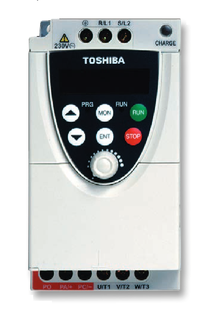
Toshiba NC1 Drive, also known as the Toshiba Tosvert VF-nC1, is a compact adjustable speed drive designed for a variety of industrial applications.
Features
The nC1 is a sub-micro, or nano-sized drive with a full range of features to meet the needs of nearly any user. The nC1 is designed to be a simple drop in replacement for a starter on an existing project or as a new installation. Either way, the nC1’s small size and full featured design make it a perfect choice for your application.
- Simple to Install : The nC1 is designed to be a drop-in replacement for a starter. The terminal arrangements for input and output power are even set up like a starter.
- Easy To Program : The nC1 uses a simple, straightforward programming menu for quick and easy setup of the drive.
- User-Friendly Operation : The nC1 comes ready to run. Simply mount the drive, run your power connections and you are ready for operation.
- Array of Communications: In today’s fast-paced manufacturing world, coordinated systems require communications from drive-to-drive and drive-to-system. Built-In RS232/RS485 Port
Specifications
| nC1 ASD Standard Specifications | ||||
| Model Range | 1001P-1007P | 2002P-2022P | 2001PL-2022PL | 2002P-2022P |
| Input Voltage Rating | 120 V/Single Phase | 230 V/Single Phase | 230 V/Three Phase | 230 V/Single Phase with RFI / EMI Filter |
| KW Range | 0.1 to 0.75 KW | 0.2 to 2.2 KW | 0.1 to 2.2 KW | 0.2 to 2.2 KW |
| HP Range | 1/8 to 1 HP | 1/4 to 3 HP | 1/8 to 3 HP | 1/4 to 3 HP |
| Overload Rating | 150% for 60 Seconds | |||
| Input Voltage Tolerance | +10%, -15% | +10%, -15% | +10%, -15% | +10%, -15% |
| Input Frequency Rating | 50/60 Hz | 50/60 Hz | 50/60 Hz | 50/60 Hz |
| Input Frequency Tolerance | ± 5% | ±5% | ±5% | ±5% |
| Output Voltage Rating | 230 V, Three Phase | |||
| Color | Munsel 5Y8 / 0.5 | |||
| Control System | Sinusoidal PWM Control | |||
| Output Voltage Range | Adjustable within a Range of 100 to 120% of Corrected Supply Voltage (200 V), Nonadjustable to any Voltage Higher than the Input Voltage | |||
| Output Frequency Range | 0.5 to 200 Hz, Default Setting: 0.5 to 80 Hz, Max Frequency: 30 to 200 Hz | |||
| Minimum Frequency Step | 0.1 Hz: Operation Panel Setting, 0.2 Hz: Analog Input (when the Max Frequency is 100 Hz) | |||
| Frequency Accuracy | Digital Setting: within ±0.5% of the Max Frequency (-10 to +50°C) | |||
| Analog Setting: within ±1.0% of the Max Frequency (25°C ± 10°C ) | ||||
| V/f Characteristics | V/f, Slip Frequency Compensation, Base Frequency, Base Frequency Voltage and Torque Boost (Adjustable Amount) | |||
| Frequency Setting Signal | Internal Pot on the Front Panel, External Frequency Signal (Connectable to a Volume with a Rated Impedance of 3 to 10 kΩ), VI Terminal (Input Impedance: 42 kΩ (Voltage: 0 to 10 Vdc) or 250 Ω (Current: 4 to 20 mAdc)). Frequency can be Set Arbitrarily Using a Two Point Setting | |||
| Startup & Jump Frequency | Adjustable within a Range of 0.5 to 10 Hz; Up to 1 Frequency can be Adjusted Together with its Widths | |||
| PWM Carrier Frequency | Selectable from among 2, 4, 8, 12, and 16 kHz (Standard Default Setting: 12 kHz or 4 kHz for Models with a Built-In EMI Noise Filter) | |||
| Accel/Decel Time | Two Selectable Accel/Decel Times Adjustable from 0.1 to 3000 seconds | |||
| Retry Operation | Selectable Number of Retries (Maximum 10 Times); If Protection Function is activated, Retry Function restarts after a main circuit check. | |||
| Electric Control | Charging of Capacitor (Deceleration Time can be Shortened by Activating Forced Shortened Deceleration Mode) | |||
| Dynamic Braking | Braking Start Frequency: 0 to Max Frequency; Braking Rate: 0 to 100%; Braking Time: 0 to 20 seconds | |||
| Input Terminal Functions | Forward/Reverse Run Input Signal, Jog Run Input Signal, Standby Signal, Preset-Speed Operation Input Signal, Reset Input Signal, etc. | |||
| Output Terminal Functions | Frequency Lower Limit Output Signal, Frequency Upper Limit Output Signal, Low-Speed Detection Output Signal, Specified Speed Attainment Output Signal, etc., Open Collector, RY Output | |||
| Failure Detection Signal | 1 Form C Contact, Rated: 250 Vac, 2A, cosØ = 0.4 | |||
| FM/AM Output | PWM Output: (1 mAdc Full-Scale DC Ammeter or 7.5 Vdc Full-Scale DC Ammeter/Rectifier-Type AC Voltmeter, 225% Current Max 1 mAdc, 7.5 Vdc Full-Scale) | |||
| Protective Function | Stall Prevention, Current Limitation, Overcurrent, Output Short Circuit, Overvoltage, Overvoltage Limitation, Undervoltage, Ground Fault, Power Supply Phase Failure, Output Phase Failure Overload Protection by Electronic Thermal Function, Armature Overload at Startup, Load-Side Overtorque at Startup, Overheating Prevention, Detection of Analog Signal Break | |||
| Momentary Power Failure Protection | Auto-Restart Control after Momentary Power Failure | |||
| Electronic Thermal Characteristics | Switching between Standard Motor/Constant- Torque VF Motor, Overload Trip, Overload Stall Selection | |||
| 4-Digit, 7-Segment LED | Frequency: Inverter Output Frequency Alarm: Stall Alarm “C,” Overvoltage Alarm “P,” Overload Alarm “L,” Overheat Alarm “H.” Status: Inverter Status (Frequency, Cause of Activation of Protective Function, Input / Output Voltage, Output Current, etc.) and Parameter Settings Free-Unit Display: Arbitrary Unit (e.g. Rotating Speed) Corresponding to Output Frequency | |||
| Indicator | Lamps Indicate Inverter Status by Lighting, such as RUN Lamp and PROGRAM Lamp | |||
| Use Environments | Indoor-Altitude: 1000 Meters (Maximum), not Exposed to Direct Sunlight, Corrosive Gas, Explosive Gas or Vibration (Less than 5.9 m2) (10 to 55 Hz) | |||
| Ambient Temperature | -10 to +50˚C | |||
| Storage Temperature | -20 to +65˚C | |||
| Relative Humidity | 20 to 93% Non-Condensing | |||
Dimensions
| Model FLA & Approximate Dimensions (Inches) & Weight (Lbs) | |||||||
| VOLTAGE | HP | MODEL NUMBER | FLA | HEIGHT | WIDTH | DEPTH | WEIGHT |
| 0.12 | VFNC1S-1001P | 0.7 | 5.6 | 2.8 | 3.9 | 2.2 | |
| 110 V | 0.25 | VFNC1S-1002P | 1.4 | 5.6 | 2.8 | 3.9 | 2.2 |
| Single Phase | 0.5 | VFNC1S-1004P | 2.4 | 5.6 | 2.8 | 3.9 | 2.2 |
| 1.0 | VFNC1S-1007P | 4.0 | 5.6 | 4.6 | 4.9 | 2.2 | |
| 0.25 | VFNC1S-2002P | 1.4 | 5.6 | 2.8 | 3.9 | 2.2 | |
| 230 V Single Phase | 0.5 1.0 2.0 | VFNC1S-2004P VFNC1S-2007P VFNC1S-2015P | 2.4 4.0 7.5 | 5.6 5.6 5.6 | 2.8 2.8 4.6 | 4.9 5.4 6.1 | 2.2 2.2 3.3 |
| 3.0 | VFNC1S-2022P | 10 | 5.6 | 4.6 | 6.1 | 3.3 | |
| 0.12 | VFNC1-2001P | 0.7 | 5.6 | 2.8 | 3.9 | 2.2 | |
| 0.25 | VFNC1-2002P | 1.4 | 5.6 | 2.8 | 3.9 | 2.2 | |
| 230 V | 0.5 | VFNC1-2004P | 2.4 | 5.6 | 2.8 | 4.9 | 2.2 |
| Three Phase | 1.0 | VFNC1-2007P | 4.0 | 5.6 | 2.8 | 5.4 | 2.2 |
| 2.0 | VFNC1-2015P | 7.5 | 5.6 | 4.6 | 6.1 | 3.3 | |
| 3.0 | VFNC1-2022P | 10 | 5.6 | 4.6 | 6.1 | 3.3 | |
| 0.25 | VFNC1S-2002PL | 1.2 | 5.6 | 2.8 | 3.9 | 2.2 | |
| 230 V | 0.5 | VFNC1S-2004PL | 2.3 | 5.6 | 2.8 | 4.9 | 2.2 |
| Single Phase Built-in RFI / EMI Filter | 1.0 2.0 | VFNC1S-2007PL VFNC1S-2015PL | 4.0 7.5 | 5.6 5.6 | 2.8 4.6 | 5.4 6.1 | 2.2 3.3 |
| 3.0 | VFNC1S-2022PL | 10.7 | 5.6 | 4.6 | 6.1 | 3.3 | |