Learn how to calculate the LRV (Lower Range Value) and URV (Upper Range Value) for DP level transmitters in open tanks, dry legs, and wet legs. Simple step-by-step guide!
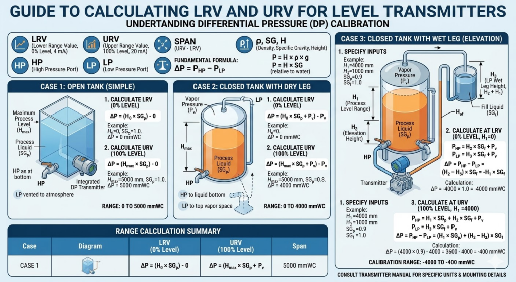
How to Calculate LRV and URV for a Level Transmitter (Step-by-Step)
If you work as an instrument technician or control systems engineer, calibrating a Differential Pressure (DP) level transmitter is a task you will face time and time again. To get an accurate 4-20mA signal to your PLC or DCS, you absolutely must know how to properly scale the transmitter.
This means knowing exactly how to calculate the LRV (Lower Range Value) and the URV (Upper Range Value).
While the math itself is just basic addition and multiplication, applying it to real-world tanks—with wet legs, dry legs, and different fluids—can get confusing fast. Today, we are going to break down how to calculate LRV and URV for level transmitters in plain English, complete with the formulas you need for every scenario.
What are LRV and URV?
Before we do any math, let’s define our terms:
- LRV (Lower Range Value): This is the pressure the transmitter sees when the tank is at 0% level (empty). This is the point where the transmitter outputs a 4 mA signal.
- URV (Upper Range Value): This is the pressure the transmitter sees when the tank is at 100% level (full). This is the point where the transmitter outputs a 20 mA signal.
To calculate these values, we use the principle of hydrostatic pressure. The golden rule formula you must remember is:
Pressure (P) = Height (H) × Specific Gravity (SG)
(Note: We measure the pressure in units like mmH2O or inH2O. Specific Gravity is the density of your fluid compared to water. Water has an SG of 1.0).
Because it is a Differential Pressure transmitter, it is always measuring the difference between the High Pressure (HP) port and the Low Pressure (LP) port: DP = HP – LP.
Scenario 1: Open Tank Measurement
This is the easiest scenario. The tank is open to the atmosphere. The transmitter’s HP side is connected to the bottom of the tank, and the LP side is left open to the atmospheric air.
Let’s set up an example:
- Maximum liquid level to measure (H): 2000 mm
- Fluid being measured: Water (SG = 1.0)
- Transmitter is mounted exactly at the bottom tapping point.
Calculating the LRV (0% Level)
When the tank is empty, there is no liquid pressing down on the HP side. The LP side is just sensing atmospheric pressure (which we count as 0 for gauge pressure).
- HP Pressure = 0 mm × 1.0 = 0 mmH2O
- LP Pressure = 0 mmH2O
- LRV = HP – LP = 0 – 0 = 0 mmH2O
Calculating the URV (100% Level)
When the tank is full, there is 2000 mm of water pressing on the HP side.
- HP Pressure = 2000 mm × 1.0 = 2000 mmH2O
- LP Pressure = 0 mmH2O
- URV = HP – LP = 2000 – 0 = 2000 mmH2O
Your calibration range for this transmitter is 0 to 2000 mmH2O.
Scenario 2: Closed Tank with a Dry Leg
When a tank is closed (pressurized), you can’t leave the LP side of the transmitter open to the atmosphere. If you did, the transmitter would measure the tank’s gas pressure plus the liquid level, giving you a falsely high reading.
To fix this, we connect the LP side to the top of the tank using a pipe. If this pipe is empty (filled only with the tank’s gas), it is called a Dry Leg.
The Math: The gas pressure pushes equally on both the liquid (HP side) and the dry leg (LP side). Because DP = HP – LP, the gas pressure cancels itself out entirely! Therefore, the LRV and URV calculations for a dry leg are exactly the same as an open tank.
Scenario 3: Closed Tank with a Wet Leg (Zero Elevation)
This is where things get interesting. Sometimes, the vapor at the top of a closed tank condenses and fills the LP pipe with liquid. To prevent erratic readings, technicians will intentionally fill this LP pipe with a reference fluid (like water or a seal liquid). This is called a Wet Leg.
Because there is a heavy column of liquid constantly pressing down on the Low Pressure (LP) side of the transmitter, the DP reading will actually be negative! This phenomenon is known in instrumentation as Zero Elevation.
Let’s set up an example:
- Measuring Level (H): 2500 mm
- Tank Fluid: Oil (SG = 0.85)
- Wet Leg Height (h): 2500 mm (LP tapping is at the very top of the 100% level mark)
- Wet Leg Fluid: Water (SG = 1.0)
Calculating the LRV (0% Level)
When the tank is empty, there is no oil on the HP side. But the wet leg is still completely full of water pressing on the LP side.
- HP Pressure = 0 mm × 0.85 = 0 mmH2O
- LP Pressure = 2500 mm × 1.0 = 2500 mmH2O
- LRV = HP – LP = 0 – 2500 = -2500 mmH2O
(At 4 mA, your transmitter must be calibrated to -2500 mmH2O).
Calculating the URV (100% Level)
When the tank is 100% full, you have 2500 mm of oil on the HP side. You still have 2500 mm of water on the LP side.
- HP Pressure = 2500 mm × 0.85 = 2125 mmH2O
- LP Pressure = 2500 mm × 1.0 = 2500 mmH2O
- URV = HP – LP = 2125 – 2500 = -375 mmH2O
Your calibration range for this wet leg transmitter is -2500 to -375 mmH2O.
What if the Transmitter is Mounted Below the Tank? (Zero Suppression)
In the real world, you can’t always mount the transmitter exactly at the bottom tapping point. Often, the transmitter is mounted on a pipe rack a few meters below the tank for easy maintenance access.
If the transmitter is mounted 500 mm below the tank, that means there is an extra 500 mm of liquid sitting in the impulse line pressing on the HP side, even when the tank is technically at 0%.
Because this adds a positive pressure to the HP side, your LRV will be a positive number instead of zero. This compensation is known as Zero Suppression.
To calculate it, simply calculate the pressure of that extra fluid height in the impulse line (Height × SG) and add it to both your LRV and your URV!
Wrapping Up
Calculating the LRV and URV for a level transmitter might look intimidating when you see terms like “Zero Elevation” or “Zero Suppression,” but if you break it down into simple mechanics, it’s just a matter of figuring out what is pushing on the High side and what is pushing on the Low side.
Always remember the golden formula: DP = HP – LP, and ensure you use the correct Specific Gravity for your fluids.

