The Delta C2000 Plus series is a high-performance, field-oriented control drive designed for complex industrial applications. Proper wiring is critical to ensure safety, longevity, and optimal performance of your VFD.
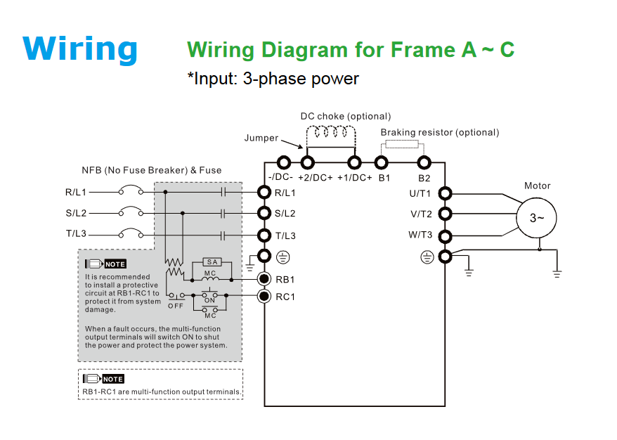
1. Power Wiring Overview
Below is the power terminal wiring diagram. Ensure that the input power supply matches the drive’s rated voltage and that proper grounding (PE) is connected to prevent electrical noise and ensure safety.
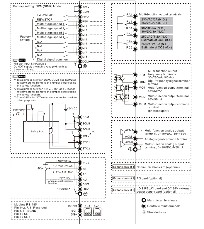
2. Control Circuit Wiring
The C2000 Plus offers versatile control terminals, including multi-function inputs (MI), analog inputs/outputs, and relay outputs. Refer to the diagram below for correct signal connection.
Delta C2000 Plus Drive Wiring Guide
Wiring Best Practices
- Separation: Always keep control signal wiring separate from power cables to minimize electromagnetic interference (EMI).
- Shielding: Use shielded twisted-pair cables for communication (RS-485) and analog signals.
- Torque: Ensure all terminal screws are tightened to the torque specifications listed in the user manual.
For other detail click here