Delta C2000 VFD Wiring Guide – A practical guide to wiring the Delta C2000 series AC drive. Includes tips for power, control terminals, and safety best practices for industrial installations.
Delta C2000 Series VFD: Complete Wiring Guide
The Delta C2000 Series is a high-performance, vector control AC motor drive designed for industrial applications. Proper wiring is essential for safe operation, precise motor control, and long equipment lifespan. This guide covers the fundamental power and control wiring requirements.
1. Safety First
Warning: Always disconnect the power supply before performing any wiring. Wait until the charging indicator LED is completely off, as hazardous voltage may remain in the DC-link capacitors even after power is removed.
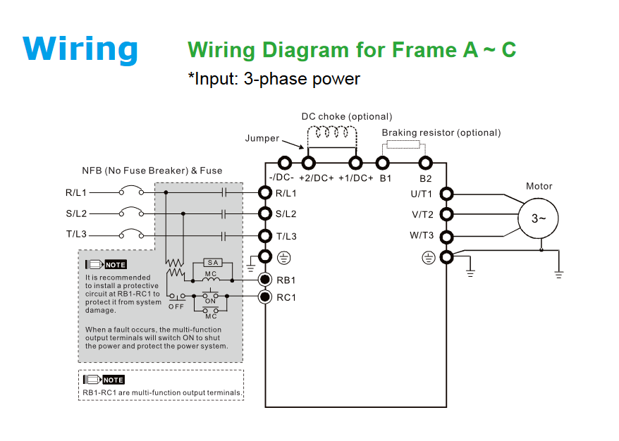
2. Power Circuit Wiring
The main circuit terminals connect the drive to the power source and the motor. Ensure you use the correct wire gauge based on the drive’s rated capacity to prevent overheating.
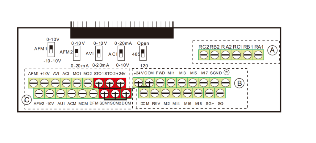
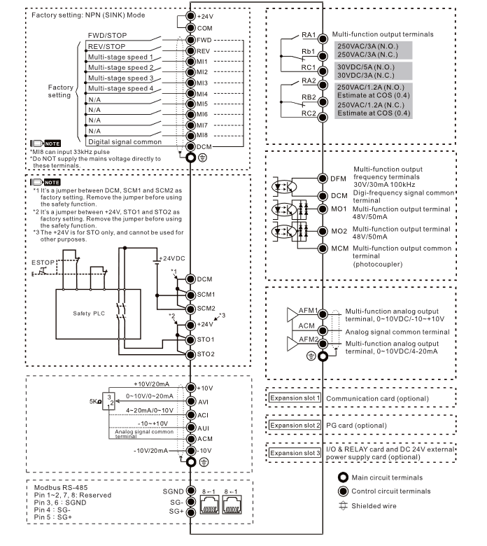
3. Control Circuit Wiring
The C2000 series offers versatile control, including digital inputs (MI), analog inputs, and relay outputs. Many users configure these for 2-wire or 3-wire control, or use a potentiometer for speed reference.
Wiring Best Practices
- Separation: Keep control signal wiring physically separated from main power cables to prevent electromagnetic interference (EMI).
- Grounding: Always connect the ground terminal to a proper earth ground to ensure safety and noise reduction.
- Shielding: Use shielded twisted-pair cables for analog signals and communication (RS-485/CANopen).
- Torque: Follow the torque specifications in your specific drive manual to ensure secure terminal connections.
For other details click here