Delta C2000 VFD Parameter Setup Guide – Easily configure your Delta C2000 series drive with this quick-reference parameter guide. Learn how to set motor data, frequency sources, and run commands.
Delta C2000 Series VFD: Essential Parameter Setup Guide
Configuring the correct parameters is crucial for the efficient operation of your Delta C2000 drive. Below is a list of the most common parameters used for initial setup and basic operation.
1. Quick Start & Factory Reset
Before programming, it is often helpful to reset the drive to factory defaults to clear any previous configurations.
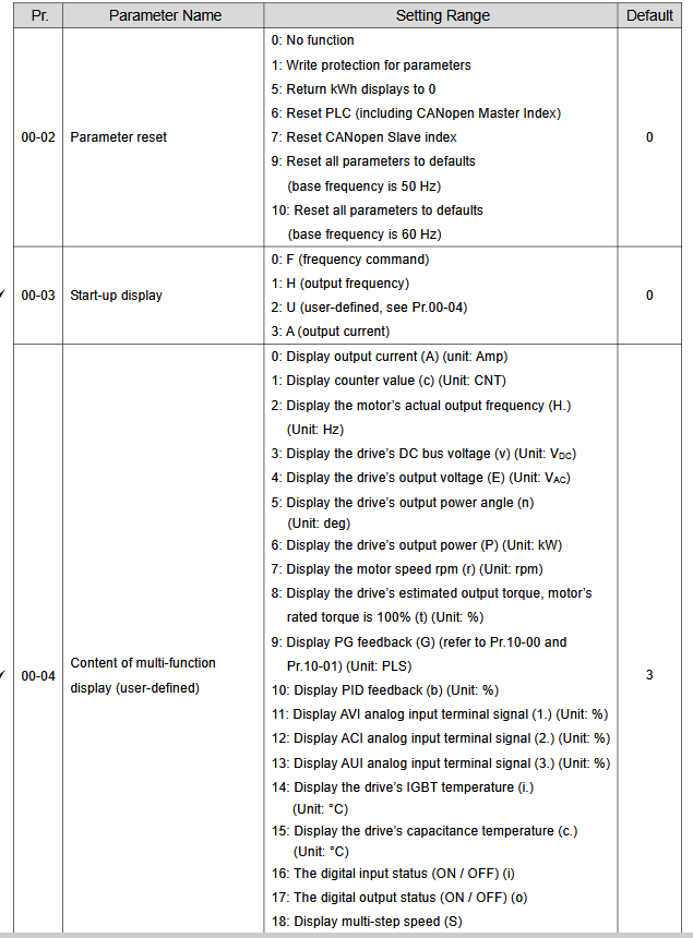
- 00-02 (Factory Reset): Set to 9 to reset all parameters to factory defaults (50Hz or 60Hz depending on your region).
2. Basic Motor Setup
Ensure these parameters match the information found on your motor’s nameplate to prevent damage and ensure performance.
- 01-00 (Max Output Frequency): Set to the maximum frequency (e.g., 50Hz or 60Hz).
- 01-01 (Max Voltage Frequency): Typically set to 50Hz or 60Hz.
- 01-02 (Max Output Voltage): Set to match your motor’s rated voltage.
3. Command & Frequency Sources
Use these settings to define how you start, stop, and control the speed of your motor.
- 00-20 (Source of Frequency Command):
- 0: Digital Keypad
- 2: Analog Input (Potentiometer)
- 00-21 (Source of Operation Command):
- 0: Digital Keypad (Run/Stop buttons)
- 1: External Terminals (Push buttons/Switches)
4. Acceleration & Deceleration
- 01-09 (Acceleration Time 1): Time in seconds to reach max frequency.
- 01-10 (Deceleration Time 1): Time in seconds to stop from max frequency.
Important Programming Tips
- Enter/Save: Always press the Enter key after changing a value to save the setting. The display will show “End” when saved.
- Navigation: Use the Menu key to access parameter groups and the Up/Down arrows to scroll through parameters.
- Safety: Always ensure the motor is at a complete stop before changing critical motor parameters.
Delta C2000 VFD Parameter List
Below list show Delta C2000 VFD Parameter List:
| Factory Reset | |||
| 00-02 | 9 | ||
| Motor Data | |||
| 05–01 | ……A | ||
| 05–02 | ……KW | ||
| 05–03 | ……rpm | ||
| ID Run | 05–00 | 0 | No function |
| 1 | Simple rolling auto-tuning for induction motor | ||
| 2 | Static auto-tuning for induction motor | ||
| 5 | Rolling auto-tuning for PM (IPM / SPM) | ||
| 12 | FOC sensorless inertia estimation | ||
| Start/Stop | |||
| 00–21 | 0 | Digital keypad | |
| 1 | External terminals | ||
| 2 | RS-485 communication input | ||
| 3 | CANopen communication card | ||
| Control Mode | |||
| 00–11 | 1 | Scaler | |
| 5 | Vector | ||
| Stop Mode | |||
| 00–22 | 0 | Ramp | |
| 1 | Coast | ||
| 2-wire/3wire | 02–00 | 1 | 2-wire |
| 3 | 3-wire | ||
| Speed Reference | |||
| 00–20 | 0 | 0: Digital keypad | |
| 1 | RS-485 communication input | ||
| 2 | External analog input (Refer to Pr.03-00) | ||
| 3 | External UP / DOWN terminal | ||
| 6 | CANopen communication card | ||
| 8 | Communication card | ||
| Motor pot | 02–07 | 19 | Digital up command MI7 |
| 02–08 | 20 | Digital down command MI8 | |
| Acc/Dec Time | |||
| 01–12 | ……s | Acceleration Time | |
| 01–13 | ……s | Deceleration Time | |
| Relay Output | |||
| RO1 | 02–13 | 1 | Indication during RUN |
| 11 | Malfunction indication | ||
| 9 | Drive is ready | ||
| RO2 | 02–13 | 1 | Indication during RUN |
| 11 | Malfunction indication | ||
| 9 | Drive is ready | ||