Getting Fault 7086 on your ABB ACS380 VFD? Learn why your Analog Input is switching from mA to Voltage mode and how to troubleshoot signal levels and wiring errors.
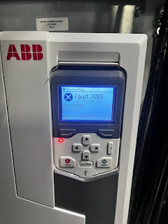
If you are working with an ABB ACS380 machinery drive and the control panel displays Fault 7086, the drive is acting to protect its sensitive internal electronics. This specific code indicates an Analog Input (AI) Overvoltage condition.
The ACS380 is designed with a unique fail-safe: when it detects a voltage spike on an input configured for current (mA), it automatically switches that input to Voltage Mode to prevent the internal shunt resistor from burning out. Here is a human-made guide to help you find the source of the overvoltage and restore your 4-20mA signals.
Understanding the “Automatic Mode Switch”
In most industrial applications, Analog Inputs are set to mA mode to receive 4-20mA signals from sensors. If a high voltage (typically above 15V-24V) is accidentally applied to these terminals, the drive detects the surge and “opens” the current loop, switching to Voltage mode.
The good news? Once the signal level returns to the acceptable range, the drive will automatically return to mA mode. However, the fault will stay in the logger until it is acknowledged.
Safety Note: Before touching control wiring, ensure you are not touching any high-voltage power terminals. While AI signals are low voltage, they are often located near 480V lines.
Step-by-Step Troubleshooting Guide
1. Check the AI Signal Levels
The first step is to use a multimeter to see what is actually arriving at the drive.
- Set your multimeter to DC Voltage.
- Measure the voltage between the AI terminal (e.g., AI1) and the AGND (Analog Ground).
- The Result: If you are measuring more than 10V DC on a line that is supposed to be 4-20mA, you have a signal source problem or a wiring error.
2. The Disconnection Test (Isolating the Drive)
You need to determine if the drive is faulty or if the external wire is carrying too much voltage.
- Action: Remove the wires from the Analog Input terminals on the drive.
- Action: Clear the fault on the keypad.
- If the fault does NOT return: The drive hardware is fine. The overvoltage is coming from your external sensor or PLC.
- If the fault RETURNS immediately: With no wires connected, this indicates a failure in the drive’s internal I/O module or a logic glitch. Try a power cycle.
3. Inspect for Common Wiring Errors
Fault 7086 is frequently caused by “human error” during installation or maintenance:
- Wrong Terminal: Check if a 24V DC supply wire was accidentally landed on the AI terminal instead of a Digital Input (DI) or a sensor excitation terminal.
- Grounding Issues: If the sensor and the drive are grounded at different potentials, a “ground loop” can cause the voltage on the signal wire to float dangerously high.
- Power Supply Mismatch: Ensure the sensor is not outputting a voltage signal while the drive is expecting a current signal.
4. Configuration Check (Parameter Group 12)
Verify that the software matches your hardware setup.
- Navigate to Parameter 12.15 (AI1 unit selection). Ensure it is set correctly (mA vs V).
- Check the physical DIP switches or jumpers on the I/O extension module (if used). On some modules, a physical switch determines the mode, and if this is set to “V” while the software is “mA,” it can cause unexpected 7086 trips.
Summary Checklist
| Checkpoint | Action Required |
|---|---|
| Multimeter Measurement | Verify signal is < 10V (for voltage) or < 20mA (for current). |
| Physical Disconnect | Remove wires to see if the fault clears. |
| Wiring Review | Look for 24V wires accidentally touching signal pins. |
| Module Seating | If using an extension module (e.g., BIO-01), ensure it is firmly clicked into place. |